华为ETP48600开关电源技术参数/报价,华为ETP48600-C8A1华为ETP48600ETP48600-D4A1高频开关电源系统48v
华为ETP48600ETP48600-D4A1高频开关电源系统48v
用户手册
注意
您购买的产品、服务或特性等应受我公司商业合同和条款的约束,本文档中描述的全部或部分产品、服务或
特性可能不在您的购买或使用范围之内。
华为ETP48200嵌入开关电源报价|技术参数_
- 简单介绍: 咨询热线:17710815462 华为ETP48200华为开关电源ETP48200,华为嵌入式电源48v200A.etp48200-c5a8 ...
ETP48300华为嵌入式开关电源 - 产品网
1、电源介绍华为ETP48300嵌入式电源系统输出电流300A,有四个50A的整流模块组成,可以选用R4850N2、R4850N6标效整流模块或者R4850G2GX整流模块。电源结构设计...
ETP48600-D4A1
概述
本文档针对直流电源系统的产品介绍、部件介绍、安装、调测、系统维护以及监控模
块和整流模块操作进行描述。
本文档中的图片仅供参考,具体结构以实物为准。
读者对象
本文档(本指南)主要适用于以下工程师:
? 销售工程师
? 技术支持工程师
? 维护工程师
符号约定
在本文中可能出现下列标志,它们所代表的含义如下。
符号 说明
用于警示紧急的危险情形,若不避免,将会导致人员死
亡或严重的人身伤害。
用于警示潜在的危险情形,若不避免,可能会导致人员
死亡或严重的人身伤害。
用于警示潜在的危险情形,若不避免,可能会导致中度
或轻微的人身伤害。
用于传递设备或环境安全警示信息,若不避免,可能会
导致设备损坏、数据丢失、设备性能降低或其它不可预
知的结果。
“注意”不涉及人身伤害。
ETP48600-D4A1
用户手册 前 言
文档版本 01 iii
符号 说明
用于突出重要/关键信息、实践和小窍门等。
“说明”不是安全警示信息,不涉及人身、设备及环境
伤害信息。
修订记录
修改记录累积了每次文档更新的说明。版本的文档包含以前所有文档版本的更新
内容。
次正式发布。
ETP48600-D4A1
用户手册 目 录
文档版本 01 iv
目 录
前 言 ................................................................................................................................................. ii
1 安全注意事项.................................................................................................................................. 1
1.1 通用安全注意事项 ..................................................................................................................................................... 1
1.2 电气安全 ..................................................................................................................................................................... 1
2 产品介绍 .......................................................................................................................................... 3
2.1 产品概述 ..................................................................................................................................................................... 3
2.2 型号说明 ..................................................................................................................................................................... 3
2.3 系统特点 ..................................................................................................................................................................... 3
2.4 工作原理 ..................................................................................................................................................................... 4
2.5 系统配置 ..................................................................................................................................................................... 4
3 部件介绍 .......................................................................................................................................... 5
3.1 结构参考 ..................................................................................................................................................................... 5
3.1.1 外观安装尺寸 .......................................................................................................................................................... 5
3.2 配电单元 ..................................................................................................................................................................... 7
3.3 整流模块 ..................................................................................................................................................................... 8
3.4 监控单元 SMU06C ................................................................................................................................................... 10
4 系统安装 ........................................................................................................................................ 14
4.1 安装前准备 ............................................................................................................................................................... 14
4.1.1 准备安装工具 ........................................................................................................................................................ 14
4.2 安装保护地线 ........................................................................................................................................................... 15
4.3 安装整流模块 ........................................................................................................................................................... 15
4.4 安装干接点信号线(可选预留)............................................................................................................................ 16
4.5 安装直流输出线缆 ................................................................................................................................................... 17
4.6 安装交流输入线缆 ................................................................................................................................................... 18
5 安装后检查 .................................................................................................................................... 19
5.1 硬件安装检查 ........................................................................................................................................................... 19
5.2 电气连接检查 ........................................................................................................................................................... 19
5.3 线缆安装检查 ........................................................................................................................................................... 19
ETP48600-D4A1
用户手册 目 录
文档版本 01 v
6 系统调测 ........................................................................................................................................ 20
6.1 交流上电 ................................................................................................................................................................... 20
6.2 选择语言 ................................................................................................................................................................... 21
6.1 设置电池参数(此项为预留供参考无需调整)
.................................................................................................... 21
6.1 母排 48V 电压参数 .................................................................................................................................................. 22
6.2 后续处理 ................................................................................................................................................................... 22
7 系统维护 ........................................................................................................................................ 23
7.1 例行维护 ................................................................................................................................................................... 23
7.2 部件维护 ................................................................................................................................................................... 23
7.3 电气原理图参考 ........................................................................................................................................................ 24
ETP48600-D4A1
用户手册 1、安全注意事项
文档版本 01 1
1 安全注意事项
1.1 通用安全注意事项
? 本产品应在符合设计规格要求的环境下使用,否则可能造成产品故障,由此引发
的产品功能异常或部件损坏不在产品质量保证范围之内。
? 负责安装、维护华为设备的人员,必须先经严格培训,了解各种安全注意事项,
掌握正确的操作方法之后,方可安装、操作和维护设备。
? 操作人员应遵守当地法规和规范。手册中的安全注意事项仅作为当地安全规范的
补充。
? 禁止在雷雨天气下操作设备和电缆。
? 操作时严禁在手腕上佩戴手表、手链、手镯、戒指等易导电物体。
? 操作过程中必须使用专用绝缘工具。
? 安装或维护操作必须符合任务的步骤顺序。
? 接触任何导体表面或端子之前使用电表测量接触点的电压,确认接触点无电压或
电压在预知的范围之内。
? 如果电源系统未连接电池,维护或故障定位时有可能导致负载(用电设备)掉
电。
? 如果电缆的储存环境温度在零度以下,在进行敷设布放操作前,必须将电缆移置
室温环境下储存 24 小时以上。
? 设备安装完成后,用户应按照用户手册要求对设备进行例行检查和维护,及时更
换故障部件,以保障设备安全运行。
1.2 电气安全
接地要求
? 安装设备时,必须首先安装保护地线;拆除设备时,必须拆除保护地线。
? 操作设备前,确保设备已可靠接地。
ETP48600-D4A1
用户手册 1、安全注意事项
文档版本 01 2
交、直流操作要求
? 电源系统供电电压为危险电压,直接接触或通过潮湿物体间接接触可能会有危险。
? 不规范、不正确的操作,可能会引起火灾或电击等意外事故。
? 设备电气连接之前,必须断开设备的前级保护开关。
? 接通交流电之前,必须确保已完成设备的电气连接。
? 连接负载(用电设备)线缆或电池线缆之前,必须确认线缆和端子的极性,以防
反接。
防静电要求
? 为防止人体静电损坏敏感元器件,在接触电路板之前,必须佩戴防静电手套或者
防静电腕带,并将防静电腕带的另一端良好接地。
? 手持单板时,必须持单板边缘不含元器件的部位,禁止用手触摸芯片。
? 拆卸下来的单板,必须用防静电包材进行包装后储存或运输。
ETP48600-D4A1
用户手册 6、系统调测
文档版本 01 3
2 产品介绍
2.1 产品概述
ETP48600-D4A1 为盒式电源,给 48V DC 系列通信设备供电,输出电流 600A;
支持提供辅电:5V/12A; 12V/10A; 24V/1A。
2.2 型号说明
ETP48600-D4A1 的型号说明如图 2-1 所示。
图2-1 型号说明
2.3 系统特点
? 电压三相范围宽 220/380V AC(三相五线:额定电压 200/346~240/415V AC)
? 完善的电池管理功能
? 网络化设计,提供一路 RS485/RS232 接口
? 支持 LCD 界面显示、按键操作
? 支持整流模块热插拔
? 整流模块功率因数值达 0.99
ETP48600-D4A1
用户手册 6、系统调测
文档版本 01 4
2.4 工作原理
电源系统工作原理示意参见附录 A
2.5 系统配置
ETP48600-D4A1 系统配置见表 2-1。
表2-1 ETP48600-D4A1 系统配置
项目 系统配置
插框
?
1U 监控单元
?
3U 整流模块安装空间与配电空间
配电单元
?
交流配电:交流三相五线输入,接线 M6 端子;3L、N、PE
?
直流配电:48V/600A ; 5V/12A; 12V/10A; 24V/1A.
监控单元 SMU06C
整流模块 可配置 12 个 R4850N 整流模块
ETP48600-D4A1
用户手册 6、系统调测
文档版本 01 5
3 部件介绍
3.1 结构参考
3.1.1 外观安装尺寸
备注:尺寸单位 mm.
ETP48600-D4A1
用户手册 6、系统调测
文档版本 01 6
ETP48600-D4A1 的内部结构如图 3-1 所示。
图3-1 ETP48600-D4A1 内部结构图
(1)SMU06C 监控 (2)R4850N 模块 1-12PSU (3)24V 模块(内置)
(4)5V//12V 模块 1 (5)5V//12V 模块 2
1
2
5
4
3
ETP48600-D4A1
用户手册 6、系统调测
文档版本 01 7
3.2 配电单元
ETP48600-D4A1 交直流配电单元如图 3-2 所示,配电规格如表 3-1 所示。
图3-2 ETP48600-D4A1 交直流配电单元
注:预留直流输出后面上出线(需要剪开预留过线孔)
注:为保证模块通风,安装后请剪去多余绝缘防护板
(1)交流输入 (2)24V 输出 (3)RS232//RS485 通讯
(4)COM 通讯 (5)5V//12V 输出 1 (6)5V//12V 输出 2
(7)48V + 极母排 (8)48V - 极母排
1 3 2
4
7
8
5 6
ETP48600-D4A1
用户手册 6、系统调测
文档版本 01 8
表3-1 配电规格
项目 配电规格
输入制式 380V AC 三相五线制:L1、L2、L3、N、PE;输入电流 70A。
交流配电 1 路交流输入接线端子
直流配电
?
48V/600A ; 5V/12A; 12V/10A; 24V/1A.
3.3 整流模块
整流模块将输入的交流电转换成稳定的 48V 直流电;辅电 5V、12V、24V。
48 v 外观
48V 整流模块的外观如图 3-3 所示。
图3-3 整流模块外观
面板
整流模块面板如图 3-4 所示。
ETP48600-D4A1
用户手册 6、系统调测
文档版本 01 9
图3-4 整流模块面板
(1)电源指示灯 (2)告警指示灯 (3)故障指示灯
(4)拨销 (5)把手
指示灯说明
整流模块指示灯说明如表 3-2 所示。
表3-2 整流模块指示灯说明
指示灯 颜色 状态 说明
电源指示灯 绿色 常亮 整流模块有交流输入
常灭 无交流输入
整流模块内部损坏
0.5Hz 闪烁 人工查询状态
4Hz 闪烁 整流模块处于应用程序加载状态
告警指示灯 黄色 常灭 整流模块无保护告警
常亮
?
环境温度过高引发的整流模块限功率
预告警
?
环境温度过高或过低保护关机告警
交流输入过欠压保护
整流模块休眠关机
0.5Hz 闪烁 整流模块与外部通讯中断
故障指示灯 红色 常灭 整流模块无故障
ETP48600-D4A1
用户手册 6、系统调测
文档版本 01 10
指示灯 颜色 状态 说明
常亮 输出过压锁死
整流模块内部故障引起的无输出
3.4 监控单元 SMU06C
外观
SMU06C 外观如图 3-5 所示。
图3-5 SMU06C 外观
面板
SMU06C 面板如图 3-6 所示。
图3-6 SMU06C 面板
(1)告警指示灯 (2)运行指示灯 (3)液晶显示屏(LCD)
(4)按键“返回” (5)按键“下” (6)按键“确认”
(7)按键“上”
表3-3 按键说明
按键标识 按键名称 说明
“ ”
“上”
按“ ”可以向上翻阅菜单或调整参数的选择值。
调整参数时,长按“ ”可以快速调整参数值。
ETP48600-D4A1
用户手册 6、系统调测
文档版本 01 11
按键标识 按键名称 说明
“ ”
“下”
按“ ”可以向下翻阅菜单或调整参数的选择值。
调整参数时,长按“ ”可以快速调整参数值。
“ ”
“返回”
按“ ”可退回上一级菜单并且不保存所设置菜单值。
“ ”
“确认”
?
在待机屏时,按“ ”可进入主菜单。
?
在主菜单中按“ ”可进入下一级子菜单。
?
在子菜单设置时按“ ”可以保存菜单选项值。
指示灯定义
SMU06C 面板指示灯说明如表 3-4 所示。
表3-4 SMU06C 面板指示灯说明
名称 颜色 状态 说明
运行指示灯 绿色 常灭 监控模块故障或无直流输入
慢闪
(0.5Hz)
监控模块正常工作,与上位机通信正常
快闪(4Hz) 监控模块正常工作,与上位机通信不正常
告警指示灯 红色 常灭 无紧急或重要告警
常亮 有紧急或重要告警
接口位置(此项供参考已经预留设备内部通信端口已经转接于设备后部,如下图)
图3-7 SMU06C 接口位置
(1)RS485/RS232 接口 (2)COM 接口 (3)干接点输出接口
(4)干接点输入接口 (5)电池温度传感器接口
ETP48600-D4A1
用户手册 6、系统调测
文档版本 01 12
(1)RS485/RS232 接口 (2)COM 接口
通信接口
SMU06C 提供了两个通信接口,接口信息如表 3-5 所示。
表3-5 SMU 通信口说明
通信口 通信参数 通信协议 用途
COM 接口 波特率:9600bit/s,
19200bit/s
MODBUS 协议 用于连接下级设
备,例如:单体
电池扫描仪、智
能空调
RS485/RS232 接
口
波特率:9600bit/s,
19200bit/s,115200bit/s
主从协议、电总
协议、MODBUS
协议
用于连接上级设
备,例如:
BBU、PSNU 等
带网管的设备
1
2
ETP48600-D4A1
用户手册 6、系统调测
文档版本 01 13
通信端口定义
引脚 通信信号 用途说明
1 COM_R+ COM 接收数据
2 COM_R-
3 NC \
4 COM_T+ COM 发送数据
5 COM_T-
6 GND 信号地
7 Force Shutdown OFF +
此功能为预留:谨慎使用。
在 OFF±引脚加入,5V~7.5V
的关机电平(需要大于
100MA 的电流驱动,不能反
接)48V 模块出现强制关机,
此时可能出现模块异常关机告
警,断开关机电平信号,48V
恢复正常告警解除。
8 Force Shutdown OFF -
9 RS485_T+ RS485 发送数据
10 RS485_T-
11 RS232_R RS232 接收数据
12 RS485_R+ RS485 接收数据
13 RS485_R
14 GND 信号地
15 RS232_T RS232 发送数据
16 NC \
ETP48600-D4A1
用户手册 6、系统调测
文档版本 01 14
4 系统安装
4.1 安装前准备
4.1.1 准备安装工具
进行安装操作之前需要提前准备好工具和仪表。
使用带绝缘手柄的工具。
---- 结束
ETP48600-D4A1
用户手册 6、系统调测
文档版本 01 15
4.2 安装保护地线
安装保护地线如图 4-1 所示。
请确保地线安装紧固,设备接地不良可能导致人身及设备伤害。
图4-1 安装保护地线
(1)采用 M6 的 OT 端子压接 16mm^2 黄绿线缆(或大于 16 方线缆)接地排。
---- 结束
4.3 安装整流模块
前提条件
? 对运抵现场的整流模块开箱验货,保证模块齐全且完好。如有问题则向当地办事
处反馈。
? 根据实际需求,移开整流模块安装空间上的假面板。
? 禁止将手伸到整流模块槽位内,以防触电。
? 整流模块运行时,背面出风口处有高温,禁止触碰或覆盖线缆及其他杂物。
操作步骤
步骤 1 向左拨动拨销。
1
ETP48600-D4A1
用户手册 6、系统调测
文档版本 01 16
步骤 2 拉出把手。
步骤 3 将整流模块插入对应槽位,沿滑道缓缓推进到位。
步骤 4 往上推进把手。
步骤 5 向右拨动拨销,锁住把手。
图4-2 安装整流模块
---- 结束
4.4 安装干接点信号线(可选预留)
操作步骤
步骤 1 用一字螺丝刀顶住干接点对应的触片,使干接点的金属弹片弹起。
步骤 2 将信号线安装到对应的干接点中。
步骤 3 收回螺丝刀,确认干接点信号线连接紧固。
图4-3 安装干接点信号线
(1)触片 (2)干接点
---- 结束
ETP48600-D4A1
用户手册 6、系统调测
文档版本 01 17
4.5 安装直流输出线缆
前提条件
? 请确保前级交流配电输入空开为 OFF 状态,并且放置“禁止操作”的显著标识。
? 在安装线缆前将所有空开都置于 OFF。
操作步骤
步骤 1 拆除配电单元的后面板。
步骤 2 布放直流输出线缆,将直流输出线缆从插框顶部环氧板穿入。
步骤 3 根据实际负载容量将直流输出负极线缆紧固到对应规格的直流输出空开。
步骤 4 将直流输出正极线缆紧固到 RTN+母排对应规格的螺丝。
图4-4 安装直流输出线缆
ETP48600-D4A1
用户手册 6、系统调测
文档版本 01 18
(1)48V 直流负载;
(2)5V;12V;24V 直流负载。
---- 结束
4.6 安装交流输入线缆
? 请确保前级交流输入空开为 OFF 状态,并且放置“禁止操作”的显著标识。
? 在安装线缆前将所有空开都置于 OFF。
ETP48600-D4A1 支持 220/380V AC 三相五线输入制式。请根据实际情况安装交流输入
线缆,建议使用 16mm^2 或更大的 600V 线缆 压接 M6 的 OT 端子。
步骤 1 打开交流输入端子防护盖,将压接好 OT 端子的交流输入线缆分别锁入对应位置;请
注意输入线缆相位,避免 L、N 反接;盖好防护盖。
步骤 2 将交流输入线缆紧固到对应的交流输入端子上,锁紧螺钉后盖好防护盖。
图4-5 安装 380V AC 三相交流输入线缆
(1) 断开交流配电箱输出 100A/4P 空开;分别用 16mm^2 线缆,PE 黄绿、L1 棕
色、L2 黑色、L3 灰色、N 蓝色、接入交流配电箱输出端。
---- 结束
ETP48600-D4A1
用户手册 6、系统调测
文档版本 01 19
5 安装后检查
5.1 硬件安装检查
? 确认所有螺丝是否拧紧(尤其要注意电气连接部分)。平垫、弹垫要齐全,且不能
装反。
? 检查整流模块是否完整的插入到插槽内,并且锁定牢固。
5.2 电气连接检查
? 检查所有空开或熔丝是否处于 OFF 状态。
? 各 OT 端子处都应安装有平垫和弹垫,确保安装牢固,OT 端子接触面无变形,接
触良好。
? 检查电池及电池线正负极连接是否正确,确保无短路。
? 检查输入、输出电源线和保护地线连接是否正确,通过测量确保输入、输出无短
路。
5.3 线缆安装检查
? 检查所有线缆的连接是否牢固可靠。
? 检查所有线缆是否理顺绑扎在就近的扎线扣上,且没有扭曲或过度弯曲。
? 检查线缆的标签是否正确,确保其没有掉落或破损的状况,且标签在同一方向,
方便查看。
ETP48600-D4A1
用户手册 6、系统调测
文档版本 01 20
6 系统调测
? 以下调测步骤都可能导致断电或产生告警,需要在操作前和操作完成后通知告警中
心。
? 设备调测过程涉及的技术内容较多,调测人员必须经过相应的技术培训。请务必参
照调测说明操作。
? 调测过程为带电作业,操作时请站在干燥的绝缘物上,不要佩戴手表、项链等金属
物品。调测中应使用经过绝缘处理的工具。
? 作业中要避免人体接触两点不同电位带电体。
? 电源设备调测中,任何“合闸操作”前一定要检查相关单元或部件的状态是否符合
要求。
? 在作业过程中,如果不容许其他人操作,配电设备上应悬挂禁止标识:“禁止合
闸,有人操作”。
? 在调测的过程中,应边调测边观察,发现异常现象要立即关机,待查明原因后,再
继续进行。
6.1 交流上电
操作步骤
步骤 1 测量交流配电箱输入空开的输入电压,三相的每相应在 176V AC~300V AC 之间,
无缺相现象。
步骤 2 将交流输入空开置于 ON,测量交流输入空开的输出电压,单相的电压应在 176V
AC~300V AC 之间,无缺相。
步骤 3 查看整流模块的运行指示灯,应为常亮状态。
步骤 4 测量-48V 母排与+48V 母排之间的电压,应在 45V DC~50V DC 之间。
---- 结束
ETP48600-D4A1
用户手册 6、系统调测
文档版本 01 21
6.2 选择语言
? 30 秒内无按键操作 LCD 背光灯关闭。
? 1 分钟内无按键操作需重新登录。
? 预设用户名为:admin,预设密码为:000001。
监控单元上电后,LCD 显示语言选择界面,通过按 或 键选择中文或 English,
按 键后进入默认的系统信息界面。
监控单元正常运行时,按如下方法修改语言。
表6-1 选择语言
主菜单 二级菜单 三级菜单 默认值 设置值
参数设置 本地参数 语言选择 中文 中文/English
6.1 设置电池参数(此项为预留供参考无需调整)
(做参考已经设置无需调整)设置“电池 1 接入”、“电池 2 接入”和“额定容量”。
表6-2 电池参数设置
主菜单 二级菜单 三级菜单 四级菜单 默认值 设置值
参数设
置
电池 基本参数 电池 1 接入 是 若实际接入 N
串电池,则电
池 1 接入~电
池 N 接入设置
为是,其余设
置为否。
电池 2 接入 是
额定容量 150Ah 每串电池的额
定容量。
说明
一个空开或熔
丝接入的电池
称为一串电
池。
ETP48600-D4A1
用户手册 6、系统调测
文档版本 01 22
6.1 母排 48V 电压参数
根据实际情况设置,通过设定电池浮充、均充电压,实现 48V 母排电压调整。
表6-3 电池参数设置
主菜单 二级菜单 三级菜单 四级菜单 默认值 设置值
参数设
置
电池 基本参数 浮充电压
49.0V 根据实际情况设置在
45V~50V 之间;
注意:1.浮充电压需要
低于均充电压视为有
效;
2. 设置电压
42.0V~58.0V 之间输出
均充电压 49.9V
? 根据实际情况设置浮充电压在 45V~50V 之间,及 48V 母排电压值;
? 注意:1.浮充电压需要低于均充电压视为有效;
? 监控功能比较多,其他功能已经设置 无需重新设置,避免异常出现。
6.2 后续处理
操作步骤
步骤 1 如果有拆下的面板或盖板,将其装回原位。
步骤 2 插框外部漆饰应保持完好,如有掉漆,掉漆部分需要立即补漆,以防止腐蚀。
步骤 3 清理现场,退出站点。
---- 结束
ETP48600-D4A1
用户手册 B、监控单元干接点告警关联
文档版本 01 23
7 系统维护
7.1 例行维护
维护人员需根据当地实际情况制定维护周期,推荐维护周期为 6 个月一次。
表7-1 日常维护列表
维护项 维护内容
检查项 检查方法 修复条件 处理方法
电气 交流输入是否
正常
万用表 交流输入电压在正
常范围之外
请参考 7.2 告
警故障处理和
7.3 部件故障
定位
电压输出是否
正常
负载支路电压超出
设定的范围(45V
DC~50V DC)
辅电:5V;12V;
24V 在正常范围。
故障巡检 指示灯是否正
常
目测 有故障报警
接地检测 电源接地点到
机柜内接地排
是否正常连接
万用表 电源接地点与接地
排之间电阻大于
0.1 欧姆
重新紧固接地
点或者更换接
地线缆
7.2 部件维护
ETP48600-D4A1
用户手册 B、监控单元干接点告警关联
文档版本 01 24
? 电源系统主要部件更换时,不允许负载断电,请做好重要负载不断电的保证措施,
例如:将主要负载空开保持在 ON,蓄电池与交流输入避免同时断开等。
? 如需断开负载,需取得客户同意。
? 整流模块可热插拔;
? 如有部件故障,请联系华为授权供应商。
---- 结束
7.3 电气原理图参考
图A-1 ETP48600-D4A1 电气原理图
HUAWEI ETP48600 switching power supply technical parameters / quotation, HUAWEI ETP48600-C8A1
HUAWEI ETP48600ETP48600-D4A1
User's Manual
Be careful
The products, services or properties you purchase should be subject to our commercial contracts and terms. All or part of the products, services, or services described in this document.
Characteristics may not be within your purchase or use.
HUAWEI ETP48200 embedded switch power supply quotation, technical parameters, Beijing friendship century import and export trade.
Brief introduction: enquiry hotline: 17710815462 HUAWEI ETP48200 HUAWEI switch power ETP48200, HUAWEI embedded power 48v200A.etp48200-c5a8...
ETP48300 HUAWEI embedded switching power supply product network
1, the power supply introduces the maximum output current of the HUAWEI ETP48300 embedded power system 300A, which consists of four 50A rectifier modules, and can choose R4850N2, R4850N6 standard effect rectifier module or R4850G2 efficient rectifier module. Power structure design...
1531118965628077.jpg
ETP48600-D4A1
Summary
This document is aimed at product introduction, component introduction, installation, adjustment, system maintenance and monitoring module for DC power system.
Block and rectifying module operation are described.
The picture in this document is for reference only. The specific structure is based on material object.
Reader object
This document is mainly applicable to the following Engineers:
Sales Engineer
Technical support engineer
? Maintenance Engineer
Symbolic agreement
The following symbols may appear in this article, which are represented as follows.
Symbolic description
A dangerous situation that can be used to alert an emergency will result in death if not avoided.
Death or serious bodily injury.
To warn potential dangerous situations, if not avoided, may lead to personnel.
Death or serious personal injury.
It can be used to warn potential dangerous situations. If not avoided, it may lead to moderate risk.
Or slight personal injury.
For transmitting equipment or environmental safety warning information, if not avoided, it may happen.
Result in equipment damage, data loss, equipment performance reduction or other non precondition.
The result of knowledge.
1531118966592673.jpg
"Attention" does not involve personal injury.
ETP48600-D4A1
Preface to the user's Manual
Document version 01 III
Symbolic description
It is used to highlight important / key information, best practices and tips.
"Note" is not a safety warning message, it does not involve personal, equipment and environment.
Damage information.
Revised record
The modification record accumulates instructions for updating each document. The latest version of the document contains updated versions of all previous documents.
Content.
The first official release.
ETP48600-D4A1
User manual directory
Document version 01 IV
1531118966357263.jpg
Catalog
Foreword...............,...,...,...,... II...
1 security precautions............,...... the...
1.1 general security precautions............ the...
1.2 electrical safety...............,......,...,...,...,...... 1
2 introduction of products.........
2.1 overview of the products......... The...
The 2.2 model tells us that...... the...
2.3 the characteristics of the system...
2.4 the principle of work............ the...
2.5 system allocation......... The...
The 3 part introduces...... the...
3.1 structure reference.........,......,......,...,...,...... 5
3.1.1 appearance installation size............,...... the...
3.2 distribution unit..................,......,......,...... 7
3.3 rectifying module...............,......,......,...,...... 8
3.4 monitoring unit SMU06C......
ETP48600-D4A1
User manual 1, safety precautions
Document version 011
1 safety precautions
1.1 general security precautions
This product should be used in the environment that meets the design specifications, otherwise it may cause product failure.
The product function or component damage is not within the scope of product quality assurance.
The personnel responsible for the installation and maintenance of HUAWEI equipment must first undergo strict training to understand all kinds of safety precautions.
Only after master the correct operation method can you install, operate and maintain the equipment.
The operator shall abide by the local regulations and regulations. The safety precautions in the manual are only used as local safety specifications.
Supplement.
It is forbidden to operate equipment and cables under thunderstorm.
It is strictly prohibited to wear watches, bracelets, bracelets, rings and other conductive objects on the wrist.
Special insulation tools must be used during operation.
Installation or maintenance operations must conform to the sequence of tasks.
Contact the surface or terminals of any conductor before using the meter to measure the voltage of the contact point, confirm that the contact point is free of voltage or
The voltage is within the foreseeing range.
If the power system is not connected to the battery, maintenance or fault location may lead to the loss of load (electrical equipment).
Electricity.
If the storage temperature of the cable is below zero, the cable must be displaced before laying operation.
Storage for more than 24 hours at room temperature.
After the installation of the equipment, users should check and maintain the equipment in accordance with the requirements of the user manual.
Replace the fault parts to ensure the safe operation of the equipment.
1.2 electrical safety
Ground requirement
When installing equipment, the protective ground wire must first be installed; when the equipment is dismantled, the protective ground must be dismantled at last.
Ensure that the equipment is reliably grounded before operating the equipment.
1531119896165814.jpg
ETP48600-D4A1
User manual 1, safety precautions
Document version 012
AC and DC operation requirements
The power supply system voltage is a dangerous voltage. Direct contact or indirect contact through wet objects may be dangerous.
Irregularities and incorrect operation may cause accidents such as fire or electric shock.
Before the electrical connection of the equipment, the front protection switch must be disconnected.
Before connecting the AC, the electrical connection of the completed equipment must be ensured.
Before connecting the load (electrical equipment) cable or battery cable, the polarity of the cable and terminal must be confirmed to prevent it.
Reverse.
Antistatic requirements
To prevent electrostatic damage to sensitive components, you must wear anti-static gloves before touching circuit boards.
Anti static wrist strap, and the other end of the anti-static wristband is well grounded.
When holding a single board, you must hold the edge of the veneer without components, and prohibit touching the chip with your hands.
The dismantled veneer must be packed, stored or transported with anti-static packaging material.
ETP48600-D4A1
User manual 6, system measurement
Document version 013
2 product introduction
A summary of 2.1 products
ETP48600-D4A1 is a cassette power supply, which supplies power to 48V DC series communication equipment, and the maximum output current is 600A.
Support to provide auxiliary power: 5V/12A; 12V/10A; 24V/1A.
2.2 model description
The model description of ETP48600-D4A1 is shown in Figure 2-1.
1531119897834563.jpg
Figure 2-1 model description
2.3 system characteristics
Voltage three phase range is 220/380V AC (three phase five wire: rated voltage 200/346 to 240/415V AC).
Perfect battery management function
The network design provides a RS485/RS232 interface.
Support LCD interface display, keystroke operation
Support rectifier module hot plug
The power factor of the rectifier module is up to 0.99
ETP48600-D4A1
User manual 6, system measurement
Document version 014
2.4 working principle
Refer to appendix A for the working principle of the power system
2.5 system configuration
The ETP48600-D4A1 system configuration is shown in table 2-1.
Table 2-1 ETP48600-D4A1 system configuration
Project system configuration
Intercalation
?
1U monitoring unit
?
Installation space and distribution space of 3U rectifier module
Distribution unit
?
AC distribution: AC three-phase five wire input, wiring M6 terminals; 3L, N, PE
?
DC distribution: 48V/600A; 5V/12A; 12V/10A; 24V/1A.
Monitoring unit SMU06C
The rectifier module can be configured with 12 R4850N rectifier modules.
ETP48600-D4A1
User manual 6, system measurement
Document version 015
1531119899200950.jpg
3 parts introduction
3.1 structure reference
3.1.1 appearance installation size
Note: size unit mm.
ETP48600-D4A1
User manual 6, system measurement
Document version 016
The internal structure of the ETP48600-D4A1 is shown in Figure 3-1.
Figure 3-1 ETP48600-D4A1 internal structure diagram
(1) SMU06C monitoring (2) R4850N module 1-12PSU (3) 24V module (built-in)
(4) 5V//12V module 1 (5) 5V//12V module 2
One
Two
Five
Four
Three
ETP48600-D4A1
User manual 6, system measurement
Document version 017
3.2 distribution unit
ETP48600-D4A1 AC and DC distribution units are shown in Figure 3-2, and the distribution specifications are shown in table 3-1.
Figure 3-2 ETP48600-D4A1 AC and DC power distribution unit
Note: reserved DC output is behind the upper outlet line (need to cut the reserved line hole).
Note: to ensure maximum ventilation of the module, remove excess insulation protection after installation.
(1) AC input (2) 24V output (3) RS232//RS485 communication
(4) COM communication (5) 5V//12V output 1 (6) 5V//12V output 2
(7) 48V + polar busbar (8) 48V - polar busbar
132
Four
Seven
Eight
56
1531119898794204.jpg
ETP48600-D4A1
User manual 6, system measurement
Document version 018
Table 3-1 distribution specifications
Project distribution specification
Input 380V AC three-phase five wire system: L1, L2, L3, N, PE; input current 70A.
AC power distribution 1
""
"Up"
Press "" to browse the menu or adjust the selection value of the parameter.
When adjusting parameters, long press "" can quickly adjust the parameter values.
ETP48600-D4A1
User manual 6, system measurement
Document version 0111
Key identification key name Description
""
"Down"
Press "" to scroll through the menu or adjust the selection value of the parameter.
When adjusting parameters, long press "" can quickly adjust the parameter values.
""
"Return"
Press "" can return to the previous menu and do not save the set menu value.
""
"Confirmation"
?
On the standby screen, press "" into the main menu.
?
In the main menu, press "" to enter the next sub menu.
?
Press menu to set menu options when setting up submenus.
Indicator light definition
The SMU06C panel indicator is shown as shown in table 3-4.
Table 3-4 SMU06C panel indicator
Name color state description
Operation indicator green frequently destroyed monitoring module failure or no DC input.
Slow flash
(0.5Hz)
The monitoring module works normally, and the communication with the upper computer is normal.
The 4Hz module works normally, and the communication with the host computer is not normal.
Alarm indicator red often extinguished without urgent or important alarm.
Always have an urgent or important warning
The location of the interface (for reference) has been reserved. The internal communication port of the device has been transferred to the rear part of the device, as shown below.
Figure 3-7 SMU06C interface position
(1) RS485/RS232 interface (2) COM interface (3) dry contact output interface
(4) dry contact input interface (5) battery temperature sensor interface.
ETP48600-D4A1
User manual 6, system measurement
Document version 0112
(1) RS485/RS232 interface (2) COM interface
communication interface
SMU06C provides two communication interfaces, and the interface information is shown in table 3-5.
Table 3-5 SMU communication port description
Use of communication protocol communication protocol for communication port
COM interface baud rate: 9600bit/s,
19200bit/s
MODBUS protocol is used to connect lower level settings
To prepare, for example: a monomer
Battery scanner, intelligence
Energy air conditioning
RS485/RS232 connection
mouth
Baud rate: 9600bit/s,
19200bit/s, 115200bit/s
Master and slave protocol, electricity general
Protocol, MODBUS
Agreement
Used to connect the superior
For example, for example:
BBU, PSNU, etc.
Equipment with network management
One
Two
ETP48600-D4A1
User manual 6, system measurement
Document version 0113
Communication port definition
Use description of pin communication signal
1 COM_R+ COM receives data
2 COM_R-
3 NC
4 COM_T+ COM sends data
5 COM_T-
6 GND signal ground
7 Force Shutdown OFF +
This function is reserved: prudent use.
Add in OFF +, 5V~7.5V
The shutdown level (need to be greater than
The current drive of 100MA can not be reversed
The 48V module is forced to turn off.
There may be an abnormal shutdown of the module at this time
Alarm, disconnect the shutdown level signal, 48V
Return to normal alarm.
8 Force Shutdown OFF -
9 RS485_T+ RS485 sends data
10 RS485_T-
11 RS232_R RS232 receives data
12 RS485_R+ RS485 receives data
13 RS485_R
14 GND signal ground
1531119898535492.jpg
15 RS232_T RS232 sends data
16 NC
ETP48600-D4A1
User manual 6, system measurement
Document version 0114
4 system installation
4.1 pre Installation Preparation
4.1.1 ready to install tools
Tools and meters should be prepared before installation.
Use a tool with an insulated handle.
- - - end
ETP48600-D4A1
User manual 6, system measurement
Document version 0115
4.2 installation of protective ground wire
The installation of a protected ground line is shown in Figure 4-1.
Please ensure that the ground wire is installed tightly, and the poor grounding of the equipment may cause injury to the body and equipment.
Figure 4-1 installing a protected ground line
(1) use the OT terminal of M6 to crimp the 16mm^2 yellow green cable (or more than 16 Fang Xianlan) grounding grid.
- - - end
4.3 installation rectifying module
Prerequisite
The inspection module of the rectifier module delivered to the scene will be opened and checked to ensure that the modules are complete and intact. Do things to the local if you have a problem
Feedback.
According to actual demand, remove the mask on the rectifier module installation space.
It is forbidden to extend the hand to the rectifying module slot to avoid electric shock.
When the rectifier module is running, there is a high temperature on the back outlet, and it is forbidden to touch or cover cables and other sundries.
Operation steps
Step 1 dial the pin to the left.
One
ETP48600-D4A1
User manual 6, system measurement
Document version 0116
Step 2 pull out the handle.
Step 3 insert the rectifier module into the corresponding slot and slowly push along the slide way.
Step 4 push up the handle.
Step 5 move the pin to the right and lock the handle.
Figure 4-2 installation rectifying module
- - - end
4.4 installation of dry contact signal line (optional reservation)
Operation steps
Step 1, use a screwdriver to hold the contact piece corresponding to the dry contact, so that the metal shrapnel of the dry contact can spring up.
Step 2 install the signal line to the corresponding dry contact point.
Step 3 reclaim the screwdriver, confirm that the dry contact signal line is fastened and fastened.
Figure 4-3 install the signal line of the contact point
(1) a contact (2) dry contact
- - - end
ETP48600-D4A1
User manual 6, system measurement
1531119897742291.jpg
Document version 0117
4.5 installation of DC output cable
Prerequisite
Please ensure that the pre stage AC distribution input is open to the OFF state, and the "prohibited operation" marked identifier is placed.
All the empty spaces are placed in OFF before installing cables.
Operation steps
Step 1 dismantle the rear panel of the distribution unit.
Step 2 lay the DC output cable, and connect the DC output cable from the epoxy board on the top of the insertion frame.
Step 3 fasten the DC output negative cable to the DC output of the corresponding specification according to the actual load capacity.
Step 4 tighten the DC output positive cable to the corresponding specification of the RTN+ bus bar.
 华为ETP48600开关电源技术参数/报价
 华为ETP48300-C9A1通信电源技术参数,华为直流高频开关电源,华为48V300A机柜嵌入式电源系统
 华为BPM-120K不间断电源技术参数,华为UPS不间断电源,华为UPS
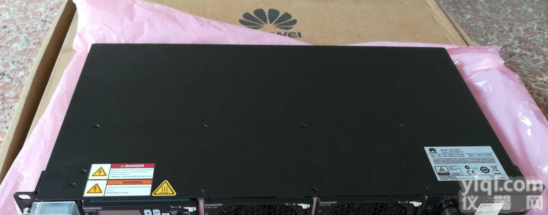 华为ETP4830-A1,嵌入式电源技术参数及简介 ,华为高频开关电源系统,48V30A通信电源系统
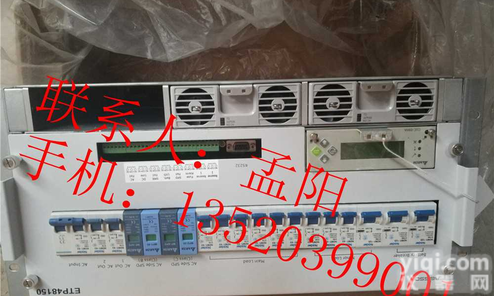 华为ETP48150嵌入式开关电源 华为48V150A通信电源/技术参数
 华为APM30,华为APM30H室外一体化高频开关电源/技术参数_阿仪网
 华为APM30,华为APM30H室外一体化高频开关电源/技术参数
 华为UPS8000-D1-200K,华为200K工频UPS电源/技术参数
 华为ETP4890开关电源ETP4890-A2嵌入式电源技术参数
 华为ETP48300嵌入式电源技术参数
 华为TP48300T室内开关电源技术参数
 华为TP48600T开关电源技术参数
本产品信息由(山东格伦德电源科技有限公司)为您提供,内容包括(华为ETP48600开关电源技术参数/报价)的品牌、型号、技术参数、详细介绍等;如果您想了解更多关于(华为ETP48600开关电源技术参数/报价)的信息,请直接联系供应商,给供应商留言。若当前页面内容侵犯到您的权益,请及时告知我们,我们将马上修改或删除。

沪公网安备 31011502008050号

