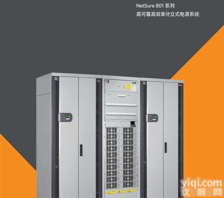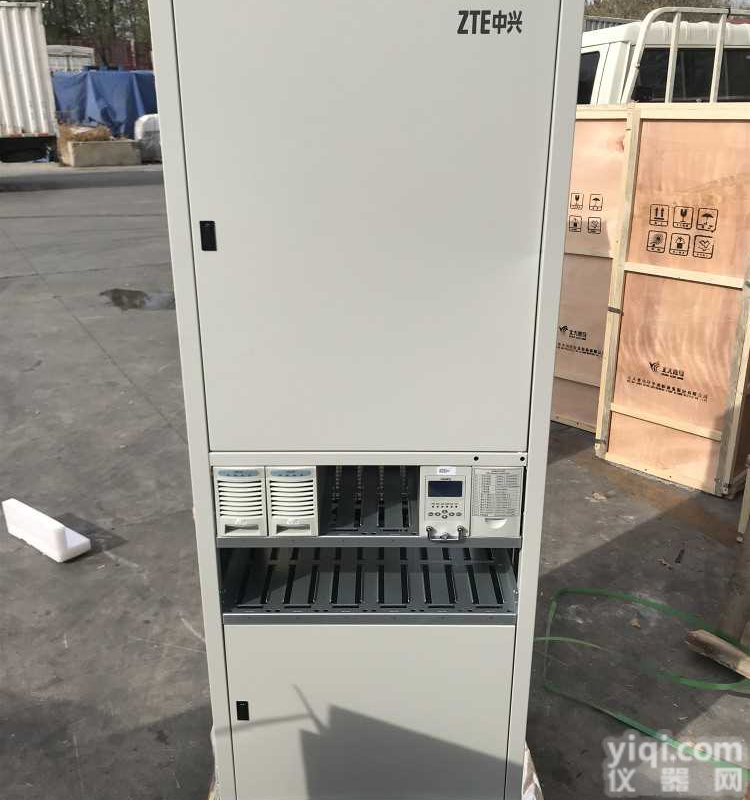
华为TP48600B开关电源柜华为TP48600B开关电源柜华为TP48600B开关电源柜华为TP48600B开关电源柜华为TP48600B开关电源柜华为TP48600B开关电源柜华为TP48600B开关电源柜华为TP48600B高频开关电源机柜华为TP48600B开关电源机柜48v通信电源 华为TP48600B-N16A2
华为TP48600B高频开关电源机柜, 华为TP48600B开关电源机柜48v通信电源 (CPMU01 )华为TP48600B-N16A2
设备类型 开关电源
设备厂家 华为
华为TP48600B机柜尺寸:
宽mm 深mm 高mm
650毫米 450毫米 1600号
设备型号 CPMU01
接口类型 DB9 公头,232 接口
接线说明 2 接 TX,3 接 RX,5 接 GND
协议名称 CPMU01华为TP48600B开关电源机柜,48v通信电源 (CPMU01 )华为TP48600B-N16A2
串口参数 地址 1,数据位 8,停止位 1,无校验,波特率 9600
注:旧版本 FSU 需配 RS232/RS485 转换器。新版本 FSU 自带 RS232(串口 7、8 为 232 接口)
可直接接入(2 接 TX,3 接 RX,5 接 GND)。需要将地址改为 1,通信方式改为 Modem,开关
电源参数设置密码:000001
铁塔智能设备接入指导
6
7) TP48600B-N16B2 (CPMU01 )
设备类型 开关电源
设备厂家 华为
设备型号 CPMU01
接口类型 RJ45 水晶头,232 接口
接线说明 水晶头 3 接 TX,7 接 RX,6 接 GND
协议名称 CPMU01
串口参数 地址 1,数据位 8,停止位 1,无校验,波特率 9600
注:旧版本 FSU 需配 RS232/RS485 转换器。新版本 FSU 自带 RS232(串口 7、8 为 232 接口)
可直接接入(3 接 TX,7 接 RX,6 接 GND)。
TP4606B;产品概述2产品框架;功能;监控模块可通过本地操作、后台网络管理等功能实现;管理功能、整流模块和分发管理;表2-4监控模块功能表;2产品拱TCP466B产品概述;LCD显示;监控模块可通过LCD液晶显示界面实时显示。显示电源系统;运行参数、运行状态、报警状态、设定参数和控制;可通过四个按键操作;(红色),提供一种驱动柜灯报警的方法,TP466B产品概述2产品架构功能监控模块可通过实际LOC实现。AL操作、后台网络管理等。介绍了环境监测、异常报警、蓄电池管理、整流模块和配电管理的功能。该函数如表2-4所示。
表2-4监控模块功能表2产品结构TP466B产品概述
液晶显示器华为TP48600B开关电源机柜,48v通信电源 (CPMU01 )华为TP48600B-N16A2
监控模块通过LCD LCD接口实时显示电力系统的AC、DC、模块和电池。
项目运行参数、运行状态、报警状态、设定参数和控制参数。参数设置与功能控制
它可以用四把钥匙操作。监控模块提供运行指示灯(绿色)和报。
(红色)同时提供驱动柜照明警示指示器输出和监控模块报警蜂鸣器输出。华为TP48600B高频开关电源机柜
TP46600
产品概述3产品和应用场景
通过调整所安装的整流模块的数量,可以灵活地将产品和应用场景的TP48 600 B电力系统应用到室内基站、室内ZY机房、BSC等。TP4606B电力系统安装安装在机房内,支撑墙(距墙100mm以上),通过调整安装整流模块的数量,可灵活应用于-48伏直流、34.8kW的负载场景。例如:BTS39 00 BTS3012室内基站BSC室内ZX室。
图3-1 TP426B电力系统应用示意图
3产品和应用场景TP466B产品概述TP48 6600电力系统和交流电源、ATS、电池等设备的典型应用,以形成现场能源解决方案,其在典型的现场解决方案中的应用如图3-2所示。图3-2 TP4266B电力系统应用在典型的现场解决方案TP466B产品概述4产品的运行和维护中采用多个优化的维护设计,使维护简单方便。操作和维护支持上、下线路。支持预维护。整流模块和监控模块都支持热插拔。监控模块的维护不会影响正常供电。内部模块可以独立拆卸和维护。华为TP48600B高频开关电源机柜, 华为TP48600B开关电源机柜48v通信电源
LCD升压反压驱动电路
在嵌入式系统里,较多场合需要LCD人机界面。分析以下LCD驱动电路。
LCD_VIN是3.6~5V,经过DC/DC burst升压得到LCD_AVDD,LCD_AVDD为LCD需要的模拟电压,根据LCD实际情况调整FB脚电压确定,这里假设是10V。
VGH是LCD的开关管的开启电压,假设这里需要15V,VGL是LCD开关管的关闭电压,假设这里需要-6.8V。
这里比较有意思的是VGH和VGL的产生。
以下给出绿、红、蓝三个节点的波形:
绿:
红:
蓝:
绿点为开关电源的开关波形,红点为绿点向上偏移10V,蓝点为绿点向下偏移10V。
绿点的电压就不分析了,开关波形。
红点波形生成过程:
华为TP48600B高频开关电源机柜
当绿点“低电平”,LCD_AVDD通过二极管1-3对C165充电,经过若干周期,C165两端电压约为LCD_AVDD,红点“低电平”。
当绿点”高电平“,根据电容两端电压不能突变,可以知道红点出现”高电平“,此时红点电压比LCD_AVDD高,二极管1-3断开,二极管3-2导通,C165放电。
蓝点波形生成过程:
当绿点“高电平”,此时通过二极管3-2对C171充电,经过若干周期,C171两端电压约为绿点”高电平“即LCD_AVDD,蓝点”高电平“。
当绿点”低电平“,根据电容两端电压不能突变,可以知道蓝点出现”低电平“,此时蓝点电压比GND低,二极管3-2断开,二极管1-3导通,C171放电。
在VGH和VGL轻负载的条件下,红点和蓝点经过RC整流可以维持在20V和-10V,并经过稳压管钳压得到目标电压。此升压和反压电路只能在清负载条件下。
LCD boost back pressure drive circuit
In embedded systems, LCD interface is needed in many occasions. The following LCD drive circuit is analyzed.
LCD_VIN is 3.6~5V, after DC/DC burst is boosted to LCD_AVDD, LCD_AVDD is the analog voltage required by LCD, and the FB foot voltage is adjusted according to the actual condition of LCD, and it is assumed to be 10V.
VGH is the opening voltage of the switch tube of LCD. Assuming that 15V is needed here, VGL is the closing voltage of the LCD switch tube, assuming that -6.8V is needed here.
What is more interesting here is the generation of VGH and VGL.
The following three waveforms of green, red and blue are given.
Green:
Red:
华为TP48600B高频开关电源机柜
Blue:
The green point is the switching waveform of the switching power supply, the red dot shifts 10V upward to the green point, and the blue point shifts 10V downward for the green dot.
The voltage of the green point is not analyzed, the switch waveform.
Red point waveform generation process:
When the green dot is "low level", LCD_AVDD charges C165 through diode 1-3. After a number of cycles, the voltage at both ends of the C165 is about LCD_AVDD, and the red point is "low level".
When the green point is "high level", the voltage can not be changed according to the voltage at both ends of the capacitor. It can be known that the red point appears "high level". At this time the red point voltage is higher than the LCD_AVDD, the diode 1-3 is broken, the diode 3-2 is on, and the C165 discharge.
Blue point waveform generation process:
华为TP48600B高频开关电源机柜
When the green point is "high level", the C171 is charged by diode 3-2 at this time. After several cycles, the voltage at both ends of the C171 is about the Green Point "high level", that is, the high level of the blue point.
When the green point is "low level", according to the capacitor at both ends of the voltage can not be mutated, it can be known that the blue point appears "low level", at this time the blue point voltage is lower than GND, diode 3-2 is disconnected, diode 1-3 conduction, and C171 discharge.
Under the condition of VGH and VGL light load, the red dot and blue dot can be maintained at 20V and -10V through RC rectification, and the target voltage can be pressed through the regulator clamp. This boost and back voltage circuit can only be operated under clear load conditions.
■电源的安全认证
电源是电脑的心脏,品质不好的电源不但会损坏主板、硬盘等部件,还会缩短电脑的正常使用寿命。当然一款品质优良的电源的售价必定不会便宜,所以有些商家往往会采用便宜电源来消费者,而有些用户自己对此并不十分了解,但区区几十元的差价可能会招致上千元的损失,这确实有些不值,所以在选购时要特别注意电源的品质是否优良。
安全标准以保障用户生命和财产安全为出发点,在原材料的绝缘、阻燃等方面作出了严格的规定。符合安全标准的产品,不仅要求产品本身符合安全标准,而且对于制作厂家也要求有较完善的安全生产体系。在这些标准中,以德国基于1EC-380标准制定的VDE-0806标准Z为严格。我国的国家标准是GB4943-1995《信息技术设备(包括电气设备)的安全》。电源符合以上标准其安全性就有了保障。电源符合某个国家的安全标准并得到其法定部门颁发的证书,比如获得UL机构颁发的证书,就称为取得了UL认证。ZG的安全认证机构是CCEE。不管是哪国的安全认证,都对爬电距离、抗电强度、漏电流、温度等方面做出了严格规定。
华为TP48600B高频开关电源机柜
爬电距离的要求
爬电距离指沿绝缘表面测得的两个导电器件之间或导电器件与设备界面之间的Z短距离。UL、CSA和VDE安全标准强调了爬电距离的安全要求,这是为了防止器件间或器件和地之间打火从而到人身安全。
抗电强度的要求
在交流输入线之间或交流输入与机壳之间由零电压加到交流1500V或直流2200V时,不击穿或拉电弧即为合格。
漏电流的要求
UL和CSA均要求暴露的、不带电的金属部分均应与大地相接。漏电流的测量是通过在这些部分与大地之间接一个1.5千欧的电阻,测其漏电流。开关电源的漏电流,在260V交流输入下,不应超过3.5mA。
温度的要求
安全标准对电器的温度要求很重视,同时要求材料有阻燃性。对开关电源来说,内部温升不应超过65℃,如果环境温度是25℃,电源的元器件的温度应小于90℃。
不符合安全标准的电源在刚开始用时对使用者并没有什么直接的不良影响,但用久了以后,由于潮湿的空气和灰尘的影响可能导致高压区短路,不但造成电源本身损坏,还会严重影响电网,从而对其他电器造成不利影响。
关于电磁干扰,国际上通用的标准有FCC-A(工业标准)、FCC-B(民用标准),电源应符合民用标准。 开关电源是把工频交流整流为直流后,再通过开关变为高频交流,其后再整流为稳定直流的一种电源,这样就有工频电源的整流波形畸变产生的噪声与开关波形产生的噪声,在输入侧泄漏出去就表现为传导噪声与辐射噪声,在输出侧泄漏出去就表现为纹波。
电磁干扰分为传导干扰和辐射干扰。传导干扰通过电源线传播,频率为30MHz以下,主要干扰音频频段。由于计算机用开关电源有金属壳作屏蔽,所以主要为传导干扰。传导干扰的大小是衡量计算机电源品质的重要标准,它包括两个方面的含义:一是防止电网上电磁干扰通过电源本身产生的电磁干扰进入电网,影响主机系统正常工作;二是防止主机本身产生的电磁干扰进入电网,影响其它电器。我们在日常工作中可能有这样的经验,在微机开机时,其附近的电器如电视、音响等不能正常使用,这是传导干扰产生的影响。
华为TP48600B高频开关电源机柜
■电源选购误区
由于ATX主板的日益流行,ATX电源取代了传统的AT电源成为市场主流,价格也从以前的两百多元降到一百多元。随着市场竞争越来越激烈,有些商家为了追求更高的利润,采用一些价格较低的劣质电源,并自圆其说地抛出些误导性言论,形成了选购误区,让消费者在购买时感到无所适从。
误区一:通过认证的电源和没有通过认证的电源质量相同。有的人告诉消费者同一品Pai的认证和非认证电源质量相同。认证电源和非认证电源是从同一工厂的同一条生产线下来的,并以此认为两者质量相同,甚至“中肯”地指出因为认证要花钱所以认证电源就要贵一些。总之,买非认证电源可以少花不少冤枉钱。但看了以上的电源知识,大家就可以发现两者有很大不同。
误区二:认为辅助5V的输出电流越大越好。有些商家向用户吹嘘自己的电源,辅助5V能达到1A,其时,有的主板甚至只要0.01A就够了。但有一点是明确的,辅助5V能提供0.72A就保证不会有事了。辅助5V因始终处于工作状态一般来说比较容易发生故障,所以它能有一个较长的寿命才是更重要的。
误区三:与Pentium Ⅲ配套。这根本就是一个性的误导,其实电源和电脑主板配套,与CPU没有关系,而Pentium Ⅲ的主板与Pentium Ⅱ的主板在技术上并没有什么区别,只要升级BIOS就行了。可以说,任何一台符合ATX 2.01的ATX电源都可和Pentium Ⅲ配套。
误区四:版本越新越好。有商家宣传自己的电源符合的Intel ATX 2.03标准,似乎要比别人优越许多。其实从ATX 2.01到ATX 2.03,只是些无关痛痒的修改,就目前来说,满足ATX 2.01标准的电源使用起来不会有问题。
误区五:功率越大越好。有些商家向用户吹嘘自己的电源功率能达到300W甚至400W。其实普通的一台多媒体电脑实际功率不足100W,而Intel新推出的Micro ATX标准也只有145W。对于普通用户,2华为TP48600B高频开关电源机柜00W的电源绰绰有余了。所以说在选购电源的时候没有必要刻意追求电源的功率大小,只要是质量合格的市售电源都可以满足多数用户的需要。
Safety authentication of power supply
The power supply is the heart of the computer. The poor quality of the power supply will not only damage the motherboard, hard disk and other components, but also shorten the normal service life of the computer. Of course, a good quality power supply will not be cheap, so some businesses often use cheap power to deceive consumers, and some users do not know it very well, but the differential of dozens of yuan may incur a loss of thousands of yuan, which is really not worth it, so we should pay special attention to the power supply when choosing. Whether the quality is good.
Safety standards are the starting point for ensuring the safety of users' lives and property, and strict regulations are made on the insulation and flame retardancy of raw materials. Products that meet safety standards require not only the product itself to meet safety standards, but also a more comprehensive safety production system for manufacturers. Among these criteria, the VDE-0806 standard based on 1EC-380 standard is the most stringent in Germany. The national standard of our country is GB4943-1995 "information technology equipment (including electrical equipment) safety". The power meets the above standards, and its security is guaranteed. The power supply conforms to the safety standard of a country and gets the certificate issued by its statutory department, such as the certificate issued by the UL agency, which is called UL certification. China's security certification body is CCEE. No matter which country's safety certification, strict regulation has been made on creepage distance, electric strength, leakage current, temperature and so on.
Requirements for creepage distance
Creepage distance refers to the shortest distance between two conductive devices along the insulation surface or between the conductive device and the device interface. The safety standards of UL, CSA and VDE emphasize the safety requirements of creepage distance, which is to prevent fire between devices and devices and thus threaten personal safety.
华为TP48600B高频开关电源机柜
Demand for resistance to electricity
When zero voltage is added to AC 1500V or DC 2200V between AC input lines or between AC input and chassis, no breakdown or arcing is acceptable.
Leakage current requirements
Both UL and CSA require that exposed and uncharged metal parts should be connected to the earth. The leakage current is measured by a 1 thousand and 500 ohm resistor between these parts and the earth, and the leakage current is measured. The leakage current of switching power supply should not exceed 3.5mA under 260V AC input.
The requirement of temperature
Safety standards attach great importance to the temperature requirements of electrical appliances, while requiring flame retardancy of materials. For switching mode power supplies, the internal temperature rise should not exceed 65 degrees. If the ambient temperature is 25 degrees, the temperature of the components of the power supply should be less than 90 degrees.
The power supply that does not meet the safety standard has no direct adverse effects on the user at the beginning of use, but after a long time, the influence of wet air and dust may lead to short circuit in high pressure area, which not only causes the damage of the power supply itself, but also seriously affects the power grid, thus causing adverse effects on other electrical appliances.
As for electromagnetic interference, the international standard is FCC-A (industrial standard) and FCC-B (civil standard), and the power supply should meet the civil standard. The switching power supply is a kind of power supply that turns the power frequency AC to DC, then turns into high frequency communication through the switch, and then rectify to a stable DC power, so that the noise generated by the distortion of the power frequency power supply and the noise produced by the switch waveform is shown as the conduction and radiation noise on the input side. The output side leaks out as a ripple.
Electromagnetic interference can be divided into conducted interference and radiation interference. Conducted interference is transmitted through the power line, less than 30MHz, mainly interfering with the audio frequency band. Because the power supply of the computer is shielded by metal shell, it is mainly conducted by interference. The size of the conduction interference is an important standard to measure the power quality of the computer. It includes two aspects: one is to prevent electromagnetic interferen华为TP48600B高频开关电源机柜ce from the power grid to enter the power grid by the electromagnetic interference produced by the power source itself, and to affect the normal work of the host system; and the two is to prevent the electromagnetic interference from the host itself into the power grid and affect other electricity. Apparatus. We may have such experience in our daily work. When the computer is opened, the electric appliances in the vicinity, such as TV and sound, can not be used normally. This is the effect of the conduction interference.
Misunderstanding of power supply
Due to the increasing popularity of ATX motherboards, the ATX power supply has replaced the traditional AT power supply as the mainstream of the market, and the price has dropped from the previous more than 200 yuan to more than 100 yuan. As the market competition is becoming more and more fierce, some merchants have adopted some low quality power supplies to pursue higher profits, and give out misleading remarks by themselves, forming a misunderstanding of buying and buying, so that consumers feel at a loss when they buy.
Myth 1: the quality of the certified power supply is the same as that of the power without authentication. Some people tell consumers that the same brand is certified and non certified power quality is the same. The authentication and non - certified power sources are from the same line in the same factory, and they think both of them are of the same quality, and even "pertinent" point out that the authentication of the power is more expensive because of the cost of authentication. In short, buying a non certified power source can cost a lot of money. But with the above knowledge of power supply, we can see that the two are very different.
Myth two: the greater the output current of auxiliary 5V, the better. Some businesses are bragging about their power supply to users, helping 5V reach 1A. At that time, some华为TP48600B高频开关电源机柜 motherboards even have enough 0.01A. But one thing is clear: auxiliary 5V can provide 0.72A to ensure that nothing will happen. Auxiliary 5V is always in work.
【导读】电源电路是一个电子产品的重要组成部分,电源电路设计的好坏,直接牵连产品性能的好坏。而电源模块Z重要的是电源电路的PCB设计,本文就为大家讲解两个电源模块电路及其PCB布局,万变不离其宗,只要弄通这两个电路和PCB布局,其它的也了然于胸了。
为什么要学习电源电路的设计? ?
华为TP48600B高频开关电源机柜
电源电路是一个电子产品的重要组成部分,电源电路设计的好坏,直接牵连产品性能的好坏。
电源电路的分类
我们电子产品的电源电路主要有线性电源和高频开关电源。从理论上讲,线性电源是用户需要多少电流,输入端就要提供多少电流;开关电源是用户需要多少功率,输入端就提供多少功率。 线性电源电路原理图举例 线性电源功率器件工作在线性状态,如我们常用的稳压芯片LM7805、LM317、SPX1117等。下图1是LM7805稳压电源电路原理图。 图1. 线性电源原理图 从图上可知,线性电源有整流、滤波、稳压、储能等功能元件组成,同时,一般用的线性电源为串联稳压电源,输出电流等于输入电流,I1=I2+I3,I3是参考端,电流很小,因此I1≈I3。我们为什么要讲电流,是因为PCB设计时,每条线的宽度不是随便设的,是要根据原理图里元件节点间的电流大小来确定的(请查《PCB设计铜铂厚度、线宽和电流关系表》)。电流大小、电流流向要搞清楚,做板才恰到好处。
Power circuit is an important part of an electronic product. The design of the power circuit directly affects the performance of the product. And the most important power module is the PCB design of the power circuit. This article explains two power module circuits and their PCB layout. It is not separated from the power module. As long as these two circuits and the PCB layout are worked out, the others are also clear.
Why do you want to learn the design of the power circuit??
The power circuit is an important part of an electronic product. The design of the power circuit directly affects the performance of the product.
The classification of power circuit
The power circuit of our electronic products is mainly composed of linear power supply and high frequency switching power supply. In theory, a linear power supply is how much current the user needs and how much current the input will provide; the switching power is how much power the user needs and how much power the input will provide. Linear power circuit schematic diagram, for example, linear power supply devices work in linear state, such as our commonly used regulator chip LM7805, LM317, SPX1117 华为TP48600B高频开关电源机柜and so on. Figure 1 below is the schematic diagram of the LM7805 voltage regulated power supply circuit. Figure 1. the principle diagram of linear power supply shows that linear power is composed of functional components such as rectification, filtering, stabilizing, energy storage and so on. At the same time, the linear power supply is generally used as a series regulated power supply, the output current is equal to the input current, I1=I2+I3, I3 is the reference end, and the current is very small, so I1 I3. Why we want to speak the current is because PCB design, the width of each line is not casual, it is determined by the size of the current between the element nodes in the principle diagram (please check the PCB design of copper platinum thickness, line width and current relation table). The size of the current and the direction of the current must be clear.
Cuk电路简介
Cuk斩波电路也称Cuk变换器。美国加州理工学院Slobodan Cuk提出的对Buck/Boost改进的单管不隔离直流变换器,在输入输出段均有电感,可以显著减小输入和输出电流的脉动,输出电压的极性和输入电压相反,输出电压既可以低于也可以高于输入电压。Cuk变换器可看做是Boost变换器和Buck变换器串联而成,合并了开关管。
开关管Q为PWM控制方式。Cuk变换器有CCM和DCM两种工作方式,但不是指电感电流,而是指流过二极管的电流连续或断续。在一个开关周期中开关管Q的截止时间(1-Dy)Ts内,若二极管电流总是大于零,则为电流连续;若二极管电流在一段时间内为零,则为电流断续工作;若二极管电流 Cuk变换器中有两个电感,这两个电感之间可以没有耦合,也可以由耦合,耦合电感可进一步减少电流脉动量。
Cuk斩波电路拓扑
当V通时,E-L1-V回路和R-L2-C-V回路分别流过电流 当V断时,E-L1-C-VD回路和R-L2-VD回路分别流过电流 输出电压极性与源电压极性相反
等效电路如图所示,相当于开关S在A、B两点之华为TP48600B高频开关电源机柜间交替切换。
稳态时电容C的电流在一周期内的平均值应为零,也就是其对时间的积分为零,即:∫icdt = 0
在图中的等效电路中,开关S合向B点时间即V处于通态的时间Ton,则电容电流和时间的乘积为i2*Ton.开关S合向A点的时间为V处于断态的时间Toff,则电容电流和时间的乘积为i1*Toff。 由此可得:i2*Ton=i1*Toff
从而可得:i2/i1=Toff/Ton=(T-Ton)/Ton =(1-α)/α 同理可得出输出电压U0与电源电压E的关系:
Cuk斩波电路的优点
输入电源电流和输出负载电流都是连续的,且脉动很小,有利于对输入,输出进行滤波。
Sepic斩波电路
SPEIC(single ended primary inductor converter) 是一种允许输出电压大于、小于或者等于输入电压的DCDC变换器。输出电压由主控开关(三极管或MOS管)的占空比控制。
Sepic斩波电路是开关电源六种基本DC/DC变换拓扑之一。
Sepic斩波电路的基本工作原理:
当V处于通态时,E—L1—V回路和C1—V—L2回路同时导电,L1和L2贮能。
V处于断态时,E—L1—C1—VD—负载(C2和R)回路及L2—VD—负载回路同时导电,此阶段E和L1既向负载供电,同时也向C1充电,C1贮存的能量在V处于通态时向L2转移。
Sepic斩波电路的输入输出关系由下式给出:
华为TP48600B高频开关电源机柜
Zeta电路
Zeta电路是开关电源六种基本DC/DC变换拓扑之一。
Zeta斩波电路也称双Sepic斩波电路,其基本工作原理是:在V处于通态期间,电源E经开关V向电感L1贮能。待V关断后,L1经VD与C1构成振荡回路,其贮存的
能量转移至C1,至振荡回路电流过零,L1上的能量全部转移至C1上之后,VD关断,C1经L2向负载供电。
Zeta斩波电路的输入输出关系为:
1. Zeta和Sepic电路相比,具有相同的输入输出关系。Sepic电路中,电源电流和负载电流均连续,有利于输入、输出滤波,反之,Zeta电路的输入、输出电流均是断续的。
2. 两种电路输出电压为正极性的。
Brief introduction of Cuk circuit
The Cuk chopper circuit is also called the Cuk converter. The Slobodan Cuk, California Institute of Technology, proposed a single tube non isolated DC converter for Buck/Boost, which has inductance in the input and output section. It can significantly reduce the pulse of input and output current, the polarity of the output voltage is opposite to the input voltage, and the output voltage can be lower than the input voltage. The Cuk converter can be regarded as a series of Boost converter and Buck converter, and the sw华为TP48600B高频开关电源机柜itch tube is merged.
The switch tube Q is the PWM control mode. The Cuk converter has two working modes, CCM and DCM, but it does not refer to the inductance current, but refers to the continuous or intermittent current flowing through the diode. In a switching period, the switch tube Q's cut-off time (1-Dy) Ts, if the diode current is always greater than zero, is continuous for the current; if the diode current is zero for a period of time, the current is interrupted, and if there are two inductors in the diode current Cuk converter, there is no coupling between the two inductors. The coupling current and coupling inductance can further reduce the current ripple.
华为TP48600B高频开关电源机柜
Cuk chopper circuit topology
When the V passes, the E-L1-V circuit and the R-L2-C-V loop flow through the current respectively when the V is broken, the E-L1-C-VD circuit and the R-L2-VD loop flow through the current output voltage polarity opposite to the source voltage polarity, respectively.
Equivalent circuit, as shown in figure, is equivalent to switch S switching between A and B alternately.
In steady state, the average value of the current of capacitor C in a cycle should be zero, that is, the integral of time to zero is zero, i.e., ICDT = 0.
In the equivalent circuit of the graph, the switch S is at B point time, that is, V is in the pass state time Ton, then the product of the capacitance current and time is the time of the i2*Ton. switch S to the A point, which is the time Toff of the V in the broken state, and the product of the capacitance current and time is i1*Toff. It can be obtained from this: i2*Ton=i1*Toff
Thus it can be obtained: i2/i1=Toff/Ton= (T-Ton) /Ton = (1- alpha) / alpha is able to get the relationship between output voltage U0 and supply voltage E:
华为TP48600B高频开关电源机柜
Advantages of Cuk chopper circuit
The input current and output load current are continuous, and the pulsation is very small, which helps to filter the input and output.
Sepic chopper circuit
SPEIC (single ended primary inductor converter) is a DCDC converter that allows output voltage greater than, less than or equal to the input voltage. The output voltage is controlled by the duty ratio of the main switch (transistor or MOS tube).
Sepic chopper circuit is one of the six basic DC/DC transform topologies of switching power supply.
The basic working principle of Sepic chopper circuit:
When V is in a state, the E - L1 - V loop and the C1 - V - L2 loop are conductive at the same time, L1 and L2 store energy.
When the V is in the broken state, the E - L1 - C1 - VD - load (C2 and R) circuits and the L2 VD - load circuit simultaneously conduct electricity. This stage E and L1 both supply the load to the load, but also charge it to the C1.
The input output relationship of the Sepic chopper circuit is given in the following way:
Zeta circuit
Zeta circuit is one of the six basic DC/DC transform topologies of switching power supply.
The Zeta chopper circuit is also known as the dual Sepic chopper circuit. Its basic working principle is that when the V is in a state, the power E can store energy through the switch V to the inductive L1. After V is shut off, L1 is constituted by VD and C1, and its storage circuit is 华为TP48600B高频开关电源机柜stored.
The energy is transferred to C1, and the current is zero across the oscillation circuit. When the energy on the L1 is transferred to C1, VD is turned off and C1 is fed to the load via L2.
The input and output relation of the Zeta chopper circuit is as follows:
1. Zeta and Sepic circuits have the same input output relationship. In the Sepic circuit, both the supply current and the load current are continuous, which is good for input and output filtering. Conversely, the input and output currents of the Zeta circuit are interrupted.华为TP48600B高频开关电源机柜
2. the output voltage of two kinds 1. classifications:
A) DC ground: DC circuit "ground", zero potential reference point;
B) AC: the zero line of the alternating current. It should be distinguished from the ground wire, but sometimes the ground wire and the zero line will be connected before pulling the electricity into the home.
C) power point: zero potential reference point of large current network device and power amplifier.
D) analog ground: zero potential reference point of amplifier, sample and hold, A/D converter and comparator.
E) digital ground: also called logic, it is the zero potential reference point of digital circuit.
F) "hot": the switching power supply does not need to use the power frequency transformer. The "ground" of the switching circuit is related to the power grid of the city, that is, the so-called "hot", and the TA is charged.
G) "cold": because the high frequency transformer of the switching power supply is isolated from the input and output terminals, and because its feedback circuit is often used as a photoelectric coupler, it can not only transmit the feedback signal, but also separate the "ground". The output of the "ground" is "cold", not charged D.
2. signal grounding
A) single point grounding: only one physical point in the whole circuit system is defined as the grounding reference point, and all other points needing grounding are received. A single point grounding is usually used in the frequency <1MHz.
The single point grounding is divided into series and parallel.
The advantage of the series grounding is that the grounding mode and the structure are simple. If the grounding wire is short, the impedance will be relatively small. The disadvantage is that if the power of a certain road is larger, the larger circuit current will be generated, and a larger pressure drop will be formed, which leads to the difference of the potential reference value between the circuit and the base area, which affects the normal work of the system.
Parallel single point grounding, the advantage is that the ground potential of each circuit is not affected by other circuits, and low impedance can effectively avoid low impedance interference between the circuit units. Disadvantages: multiple grounding lines are needed, the length of ground wire is increased, thus increasing the earth impedance, and the coupling of the ground wires will also be caused.
B) multi point grounding: all the grounding points are directly connected to the nearest ground plane (i.e. the metal bottom plate) of the TA, which is usually >10MHz.
C) floats: there is no conductor connection between the earth and the earth. [virtual ground: no earth, but equal potential.
D) mixed grounding
Figure 5 and Figure 6 provide two kinds of mixed grounding methods. For capacitive coupled circuits, the single point grounding structure appears at low frequencies, and the multi point grounding state occurs at high frequencies. This is because the capacitor diverts the high frequency current to the ground. The key to the success of this method lies in the frequency of clear use and the expected direction of ground current. The use of capacitance and inductance in the grounding topology enables us to control RF current in an optimized way. The wiring of PCB can be controlled by determining the path to be passed by RF current.
3. equipment grounding purpose
A) good electrical connection between metal shell and grounding device in protected area.
B) prevent static electricity from grounding, release the accumulated charges on the chassis, avoid accumulation of charges and raise the potential.
C) shields the device from the external electromagnetic environment, so that the potential of the equipment changes to the earth.of circuits is positive.
华为TP48600B高频开关电源机柜
 中兴ZXDU58 B900开关电源技术参数/报价
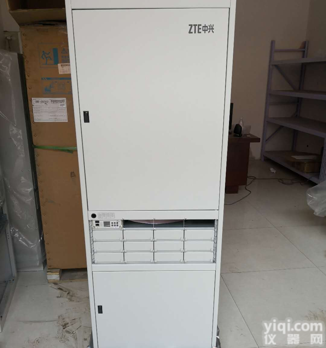 中兴ZXDU68 T601高频开关电源柜,中兴通信电源技术要求
 中兴ZXDU68 S601室内高频开关电源技术参数
 ZXDU68B201 中兴ZXDU68B201开关电源技术参数
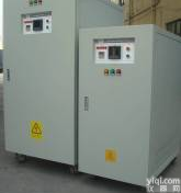 600V10A直流电源600V20A高压可调电源600V30A直流电源,电压0-1000V,开关电源技术-可调直流电源
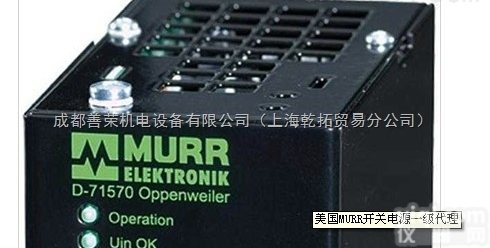 好价格MURR开关电源,穆尔开关电源技术文章
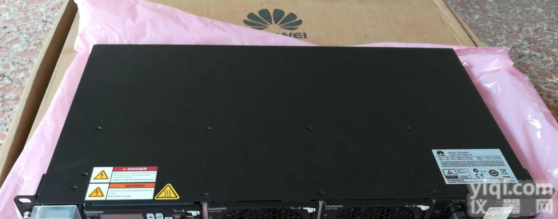 华为ETP4830-A1,嵌入式电源技术参数及简介 ,华为高频开关电源系统,48V30A通信电源系统
 华为ETP48300-C9A1通信电源技术参数,华为直流高频开关电源,华为48V300A机柜嵌入式电源系统
 XM-800 高压开关特性测试仪(高品质恒压开关电源技术)
 PISA11.406 PULS电源技术参数开关电源
 华为ETP4890开关电源ETP4890-A2嵌入式电源技术参数
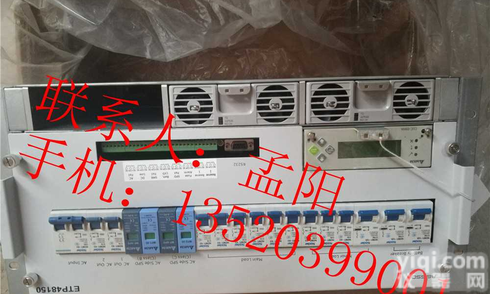 华为ETP48150嵌入式开关电源 华为48V150A通信电源/技术参数
本产品信息由(山东格伦德电源科技有限公司)为您提供,内容包括(中兴ZXDU58 B900开关电源技术参数/报价)的品牌、型号、技术参数、详细介绍等;如果您想了解更多关于(中兴ZXDU58 B900开关电源技术参数/报价)的信息,请直接联系供应商,给供应商留言。若当前页面内容侵犯到您的权益,请及时告知我们,我们将马上修改或删除。

关注微信公众号

微信小程序
