
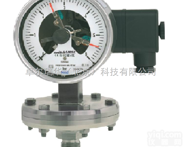
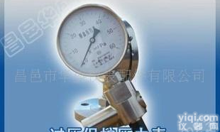
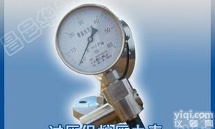
| 类型: | 隔膜压力表 | 型号: | 432.56.100-831.21 |
| 联接型式: | G1/2 | 精度等级: | 1.0 |
| 品Pai: | WIKA/威卡 | 环境温度: | -40-70(℃) |
| 加工定制: | 是 | 公称直径: | 100 160(mm) |
| 测量范围: | 0-400Mbar(MPa) |
WIKA 432.56.100-831.21
带过压保护膜片式不锈钢电接点压力表
Diaphragm pressure gauge
with switch contacts
Model 432.56,
high overpressure safety up to 100 bar
Model 432.36, safety version, high overpressure safety up to 400 bar

Diaphragm pressure gauge model 432.56.100,
high overpressure safety up to 40 bar, with switch
contact model 831.21
Applications
Control and regulation of industrial processes at measuring points with increased overpressure and scale ranges from 0 … 25 mbar
Monitoring of plants and switching of electric circuits
For gaseous and liquid, aggressive and highly viscous or contaminated media, also in aggressive ambience
Process industry: Chemical, petrochemical, power plants, mining, on- and offshore, environmental technology, machine building and general plant construction
Special features
High overpressure safety, optionally up to 40, 100 or 400 bar, due to metallic diaphragm cushion, without liquidfilled measuring cell
Wide choice of special materials
Also available with liquid-filled case for high dynamic pressure loads or vibrations
Gauges with inductive contacts for use in hazardous areas with ATEX approval
Gauges with electronic contact for PLC applications
Description
Wherever the process pressure has to be indicated locally, and, at the same time, circuits are to be made or broken, the model 432.56 or 432.36 switchGAUGE can be used.
Switch contacts (electrical alarm contacts) make or break an electric control circuit dependent upon the position of the instrument pointer. The switch contacts are adjustable over the full extent of the scale range (see DIN 16085), and are
mounted predominantly below the dial, though also partly on top of the dial. The instrument pointer (actual value pointer) moves freely across the entire scale range, independent ofthe setting.
The set pointer can be adjusted using a removable adjustment key in the window.
Switch contacts consisting of several contacts can also be set to a single set point. Contact actuation is made when the actual value pointer travels beyond or below the desired set point.
The pressure gauge is manufactured in accordance with DIN 16085 and fulfils all requirements of the relevant standards (EN 837-3) and regulations for the on-site display of the working pressure of pressure vessels.
As switch contacts magnetic snap-action contacts, reed switches, inductive contacts - for requirements to ATEX - or electronic contacts for triggering a PLC are available.
For further information on the different switch contacts please
see data sheet AC 08.01.
Standard version
Nominal size in mm
100, 160
Accuracy class
1.6
Scale ranges
0 ... 25 mbar to 0 ... 250 mbar (flange Ø 160 mm) 1)
0 ... 400 mbar to 0 ... 40 bar (flange Ø 100 mm) 1)
or all other equivalent vacuum or combined pressure and vacuum ranges
Pressure limitation
Steady: Full scale value
Fluctuating: 0.9 x full scale value
Overpressure safety
40, 100 or 400 bar
Permissible temperature
Ambient: -20 … +60 °C
Medium: +100 °C maximum
Temperature effect
When the temperature of the measuring system deviates from the reference temperature (+20 °C):
max. ±0.8 %/10 K of full scale value
Process connection with lower measuring flange
Stainless steel 316L, G ½ B (male), 27 mm flats
Pressure element
≤ 0.25 bar: Stainless steel 316L
> 0.25 bar: NiCr-alloy (Inconel)
Pressure chamber sealing
FPM/FKM
Movement
Stainless steel
Dial
Aluminium, white, black lettering
Pointer
Instrument pointer: Aluminium, black
Set pointer: red
Case
Stainless steel, gauges with liquid filling with compensating valve to vent case
Model 432.56: with blow-out device
Model 432.36: safety version with solid baffle wall and blow-out back
Upper measuring flange
≤ 0.25 bar: Chrome steel
> 0.25 bar: NiCr-alloy
Window
Laminated safety glass
Bezel ring
Cam ring (bayonet type), stainless steel
Electrical connection
Terminal box
Ingress protection
IP 54 per EN 60529 / IEC 529
Switch contacts
Magnetic snap-action contact model 821
No control unit and no extra power supply required
Direct switching up to 250 V, 1 A
Up to 4 switch contacts per measuring instrument
Inductive contact model 831
Long service life due to non-contact sensor
Additional control unit required (model 904)
With corresponding control unit suitable for use in zone 1 /21 (2 GD) hazardous areas
Low effect on the indication accuracy
Fail-safe switching at high switching rates
Insensitive to corrosion
Up to 3 switch contacts per measuring instrument
Electronic contact model 830 E
For direct triggering of a programmable logic controller(PLC)
2-wire system (option: 3-wire system)
Long service life due to non-contact sensor
Low effect on the indication accuracy
Fail-safe switching at high switching rates
Insensitive to corrosion
Up to 3 switch contacts per measuring instrument
Reed switch model 851
No control unit and no extra power supply required
Direct switching up to 250 V, 1 A
Also suitable for direct triggering of a programmable logic controller (PLC)
Free from wear as without contact
Up to two change-over contacts per measuring instrument
Switching function
The switching function of the switch is indicated by function index 1, 2 or 3.
Model 8xx.1: Contact makes (clockwise pointer motion)
Model 8xx.2: Contact breaks (clockwise pointer motion)
Models 821.3 and 851.3: Change over; one contact breaks and one contact makes simultaneously when pointer reaches set point
For further information please see data sheet AC 08.01, electrical switch contacts
Options
Other process connection
Sealings (model 910.17, see data sheet AC 09.08)
Liquid filling (models 433.56, 433.36, ingress protection IP 65)
Vacuum safe to -1 bar
Max. medium temperature +200 °C
Higher indication accuracy, class 1.0
Open connecting flanges per DIN/ASME from DN 15 to DN 80 (preferred nominal widths DN 25 and 50 or DN 1" and 2"; see data sheet IN 00.10)
Wetted parts made of special materials, high overpressure safety up to 10 bar(flange Ø 160 mm) or 40 bar (flange Ø 100 mm): PTFE (models 452.56, 452.36), Hasloy, Monel, nickel, tantalum, titanium (accuracy class 2.5)
Inductive contacts also in safety version (SN, S1N)
Special version
Model 432.36, high overpressure safety up to 400 bar
Scale ranges:
0 ... 25 mbar to 0 ... 250 mbar (flange Ø 190 mm)
0 ... 400 mbar to 0 ... 40 bar (flange Ø 120 mm)
Flange connecting screws: Steel, corrosion-protected
CE conformity
Pressure equipment directive
97/23/EC, PS > 200 bar, module A, pressure accessory
EMC directive
2004/108/EC, EN 61326 emission (group 1, class B) and interference immunity (industrial application)
ATEX directive 1)
94/9/EC, II 2 G Ex ia IIC
Approvals 1)
ATEX, Design approval for connection to hazardous zone 0
GOST, metrology/measurement technology, Russia
GOST-R, import certificate, Russia
KOSHA, ignition protection type „i“ - intrinsic safety, South Korea
CRN, safety (e.g. electr. safety, overpressure, ...), Canada
Certificates 1)
2.2 test report per EN 10204 (e.g. state-of-the-art manufacturing, material proof, indication accuracy)
3.1 inspection certificate per EN 10204 (e.g. material proof
wetted parts metal component, indication accuracy)
1) Option
Approvals and certificates, see website
Dimensions in mm
switchGAUGE model 432.56.100, with switch contact model 821, 831 or 830 E

switchGAUGE model 432.56.160, with switch contact model 821, 831 or830 E
Option
switchGAUGE model 432.36.100, with switch contact model 821, 831 or 830 E
Option
switchGAUGE model 432.36.160, with switch contact model 821, 831 or 830 E
Dimensions in mm
switchGAUGE model 432.56.100, with switch contact model 851.3 or 851.33
switchGAUGE model 432.56.160, with switch contact model 851.3 or 851.33
Option
switchGAUGE model 432.36.100, with switch contact model 851.3 or 851.33
Option
switchGAUGE model 432.36.160, with switch contact model 851.3 or 851.33
Ordering information
Model / Nominal size / Overpressure safety up to ... bar / Scale range / Type of contact and switching function / Connection
size / Options
 432.56.100 WIKA 432.56.100-831.21 带过压保护膜片式不锈钢电...
DC-CTB-1 电流互感器过压保护器
432.56.100 WIKA 432.56.100-831.21 带过压保护膜片式不锈钢电...
DC-CTB-1 电流互感器过压保护器
 LODESTAR 乐达 LD3801A LODESTAR 乐达 LD3801A掌上型数字 万用表(带蜂鸣) 过压保护
 ZL-CTB 特荐 湖南 过电压保护器 ZL-CTB电流互感器过压保护器
 DC-CTB-1 DC-CTB-1电流互感器过压保护器 过电压保护器原理 价格
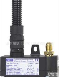 WIKA 陶瓷差压变送器 890.09.2190 2.5倍过压保护 原装进口高品质
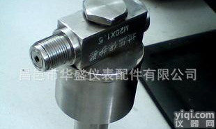
 生产压力表过压保护器、40MPA
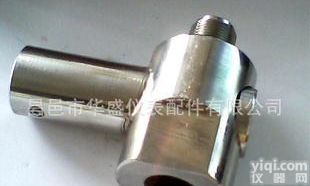
 公司生产压力表微压过压保护器。如图(1)
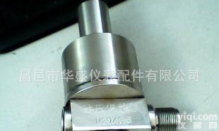 公司生产压力表过压保护器,20KPA 如图()
 公司生产压力表过压保护器, 30MPA如图
 大量生产微压过压保护器、过压保护器、 如图
 公司生产压力表过压保护器,
本产品信息由(卓尔瑞华(北京)科技有限公司)为您提供,内容包括(432.56.100 WIKA 432.56.100-831.21 带过压保护膜片式不锈钢电...)的品牌、型号、技术参数、详细介绍等;如果您想了解更多关于(432.56.100 WIKA 432.56.100-831.21 带过压保护膜片式不锈钢电...)的信息,请直接联系供应商,给供应商留言。若当前页面内容侵犯到您的权益,请及时告知我们,我们将马上修改或删除。


