CFM101CXXX-DR Series MODEL | OUTPUT VOLTAGE | MAX. LOAD | MIN. LOAD | RIPPLE & NOISE | VOLTAGE ACCURACY | LINE REGULATION | LOAD REGULATION | % EFF. (Typ.) | PF (Typ. ) |
CFM101C120-DR | 12V | 8.4A | 0A | 1% | ±1% | ±0.5% | ±1% | 87% | 0.9 |
CFM101C150-DR | 15V | 6.7A | 0A | 1% | ±1% | ±0.5% | ±1% | 87% | 0.9 |
CFM101C200-DR | 20V | | 0A | 1% | ±1% | ±0.5% | ±1% | 88% | 0.9 |
CFM101C240-DR | 24V | 4.2A | 0A | 1% | ±1% | ±0.5% | ±1% | 88% | 0.9 |
CFM101C480-DR | 48V | 2.1A | 0A | 1% | ±1% | ±0.5% | ±1% | 90% | 0.9 |
INPUT SPECIFICATIONS: | |
Voltage …....………........…................................................ 90~264Vac | |
Frequency …………………………..………..…………..... 47 to 63Hz | |
Inrush Current ………………….……..................... 50A max. @240Vac | |
Conducted EMI ………………………..….…… CISPR/FCC Class B | |
Leakage Current ………………………..…..……….…...…… 3.5mA max. | |
OUTPUT SPECIFICATIONS: | |
Holdup Time ………………………..…..……………….… 8ms typ. @115Vac | |
Short Circuit Protection …………….….....…... Hiccup Mode (Auto Recover) | |
Over Voltage Protection …………..……...…….... TVS Component to Clamp | |
Temperature Coefficient …………..…………............................... ±0.05%/℃ | |
GENERAL SPECIFICATIONS: | |
Isolation ……………………………………...…… Input to output = 4,242VDC | |
Operating Temperature …….. CFM40C/60CXXX-DR 0 ~ 50℃℃ (see Derating Curve) | |
CFM101CXXX-DR 0~ 40℃℃ (see Derating Curve) | |
Storage Temperature …………………………....….......…........ -20~85℃℃ | |
Humidity ..................................................... 93% RH max. Non-Condensing | |
Cooling …………………..…..…………………..……..... Natural Convection | |
Switching Frequency …………..… CFM40C/60CXXX-DR 66KHz Typical | |
CFM40101CXXX-DR 100KHz Typical | |
MTBF ……………….… MIL-HDBK-217F, GB, 25℃/115VAC …… T.B.D hrs | |
Altitude ……………….……..……………………….…………………… 2000m | |
Dimensions …….….. 5.433x2.323x1.894inches (138.00x59.00x48.10mm) | |
Weight ……………………………..………..………………………… 475g | NOTE: | |
SAFETY AND EMC: | 1. Add a 0.1uF ceramic capacitor and a 10uF E.L. capacitor to | |
Emission and Immunity …………... EN55022 Class B, FCC Part 15 Class B | output for Ripple & Noise measuring @20MHz BW. | |
EN61000-6-3, EN61000-3-2, EN61000-3-3 | 2. Line regulation is measured from High Line to Low Line with full load. | |
EN55024, EN61204-3, EN61000-6-1 | 3. Load regulation is measured from full to 10% load. | |
Safety ………………………..……… IEC60950-1, EN60950-1, UL60950-1 | 4. CFM40C/60C/101C Input connector mates with DECA | |
T40MBB27-03 (Pitch 6.35mm) 3pin positions terminal blocks. | |
5. CFM40C/60C/101C Output connector mates with DECA | |
T40MBB27-04 (Pitch 6.35mm) 4pin positions terminal blo | |

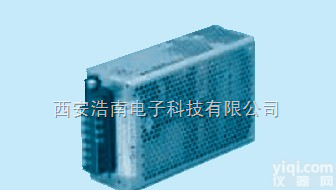
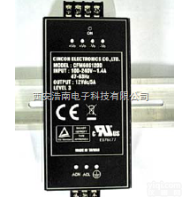 CFM40C240-DR,CFM101C CNCON导轨式开关电源CFM40C/60C/100C系列
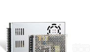
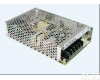 DRP-240-24台湾明纬导轨式开关电源 DRP-240-24台湾明纬导轨式开关电源
 KHEA120F-24 KHEA240F KH系列AC-DC导轨式开关电源 DIN安装电源 KHEA120F-2...
 施耐德优化型导轨式开关电源 付艳芳
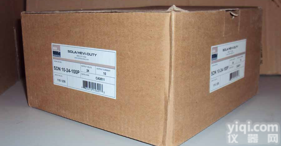 供应美国SOLA SDN10-24-100P导轨式开关电源
 都匀导轨式开关电源|指针式温度控制器|产品的详细参数,实时报价
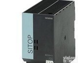 SITOP导轨式开关电源6EP1931-2EC42
 导轨式开关电源
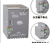 PS5R-SB24,新品IDEC和泉导轨式开关电源
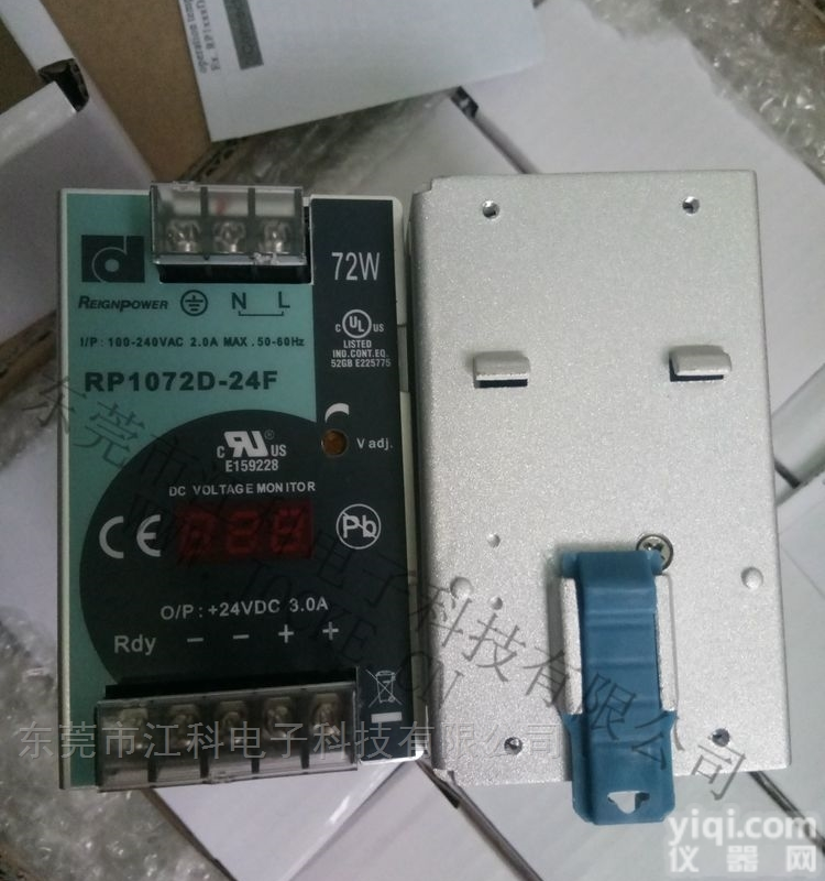 RP1072D-24FTNDA 台湾昂鼎导轨式开关电源带数显
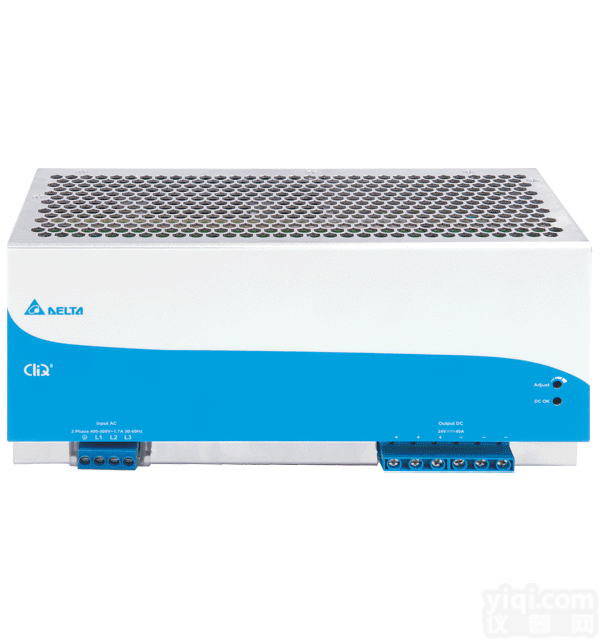 DRP024V960W3BN 台达导轨式开关电源960W 24VDC输出