| COMPLIANCE STANDARD | EN 60079-0, EN 60079-1, EN 60079-7,
EN 60079-15, EN 61241-0, EN 61241-1
EN 61241-1, IEC 60079-0, IEC 60079-1,
IEC 61241-0, IEC 61241-1 & IEC 60529 |  |
| CERTIFICATION | ATEX II 2 GD Ex d IIC / Ex e II / Ex tD A21
II 3 GD Ex nR II
IECEx Ex d IIC / Ex e II / Ex tD A21
GOST-R Ex d IICU / Ex e IIU
CSA Ex d IIC / Ex e II Class I Zone 1
Class I Division 2, Groups A, B, C & D
Class II Division 2, Groups E, F & G
Class III, Enclosure Types 3, 4 & 4X
NEPSI Ex d IIC / Ex e II
INMETRO BR - Ex d IIC / Ex e II / Ex nR II / Ex tD A21
ABS 1-1-4/7.7, 4.8-3/1.7, 4-8-3/13 and 4-8-4/27.5
MODU Rules 4-3-3/9
LLOYD’S Enclosure Systems (Part 1B)
RMRS Part XI of Rules for sea-going ships (ed.2008) |
| CERTIFICATE | ATEX BAS 01ATEX2271X & SIRA 09ATEX1221X
IECEx SIR 07.0099X
GOST-R POCC GB.06.00853
CSA CSA 1356011
NEPSI GYJ06189X
INMETRO NCC 5877/09 X
ABS 09-LD463991-PDA
LLOYD’S 10/00056
RMRS 09.00784.011 |
| IP RATING | IP66 & IP68 (25 metres - 30 minutes), NEMA 4X & DTS01 1991 |
| APPLICATION | | EExd Equipment | CR-1B type glands will only maintain Flameproof Exd integrity when used with cable that is substantially round and
compact with extruded bedding. The cable shall be deemed to be effectively filled. Ref: IEC60079-14:2002 Section 10.4.2 | Gas Group | Internal Ignition Source | Enclosure Volume | Which Zone | Use Type CR-1B Gland | IIC, IIB, IIA | NO | Any | Zone 1 or 2 | YES | IIB, IIA | YES | Any | Zone 2 | YES | IIB, IIA | YES | 2 litres or less | Zone 1 | YES |
EExe Equipment |
Other Equipment | | Gas Group II, Zones 1 and 2 | Ignitable Dust, Zones 21 and 22 |
|
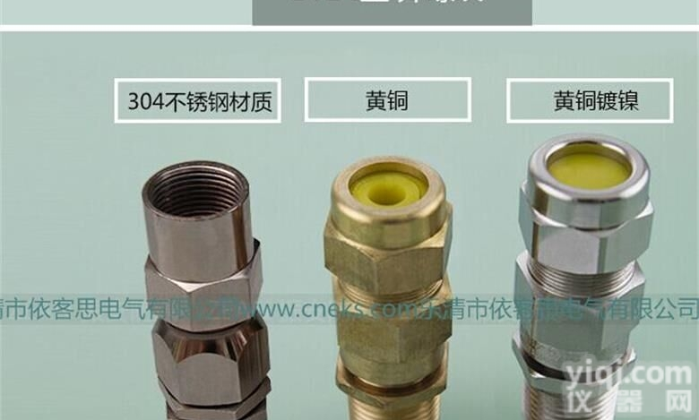
| MATERIALS | Brass CZ121 (CR-*B)
316 Stainless Steel (CR-*S)
Inner & outer sheath material: Standard (CR-1) Neoprene, black. Option (CR-3) Silicone, white.
Reduced bore outer sheath seal (R) Silicone, red. (CR-**R)
Entry thread seal: Nitrile is supplied with neoprene seal version. Silicone is supplied with silicone seal version |
| VARIATIONS | For Lead Sheath Cables the gland is fitted with a metallic continuity washer:
Brass (CR-2B); 316 Stainless Steel (CR-2S)
Omission of outer seal: Brass (CR-DB); Stainless Steel (CR-DS)
Omission of inner seal [Exe Only]: Brass (CR-OB); Stainless Steel (CR-OS) |
| EXAMPLE PART NUMBERING | Sample: CR-1B R K1/ZP/20S/M20
CR-1:
CR-* - Gland type
**1 - Seal material (Neoprene)
B - Body material (Brass)
R - Reduced bore outer seal
K1 - Supplied complete with accessories (PVC Shroud)
ZP - Zinc plating
20s - Gland size with regards to cable acceptance range
M20 - Entry thread |
| OPTIONS | R | Reduced Bore Seal |
| C | PVC Shroud (C) - PCP Shroud (P) - LSOH Shroud (3) |
| K or V | Locknut, Earth Tag & Nylon (K) or Fibre (V) IP Washer |
| S | Including Serrated Washer |
| 1 | Quantity per kit |
| NP | Nickel Plated (NP) - Zinc Plated (ZP) |
OPERATING
TEMPERATURES | Standard Seals -20ºC to +85ºC
Silicone Seals -60ºC to +180ºC |
| OPTIONAL ACCESSORIES | Locknut: Brass (ACBLN) / Stainless Steel (ACSLN)
Earth tag: Brass (ACBET) / Stainless Steel (ACSET)
IP Washers: Nylon (ACNSW) / Fibre (ACFSW) / PTFE (ACPSW)
Serrated Washer: Stainless Steel (ACSSW)
Shrouds: PVC (ACSPVC) / PCP (ACSPCP) / LSOH (ACSSIO) |
| Gland Size | | Entry Threads | | Metric | NPT/BSP |
| Entry Thread Length
[B] | Max Across Corners
[A] | Max Protrusion Length | | Gland Seal Range | | Cable Inner Sheath [C] | | Cable Outer Sheath [D] | | Standard | Reduced (R) |
| | Min | Max | Min | Max | Min | Max |
| Armour Acceptance Range | Shroud Size |
|
| 16 | M20 | 1/2" or
3/4" | 16 | 28.0 | 78.0 | 3.4 | 8.4 | 9.0 | 13.5 | 6.7 | 10.3 | 0.15 - 1.25 | EL24 | | 20s | M20 | 1/2" or
3/4" | 16 | 28.0 | 78.0 | 7.2 | 11.7 | 12.9 | 16.0 | 9.4 | 12.5 | 0.15 - 1.25 | EL24 | | 20 | M20 | 1/2" or
3/4" | 16 | 33.0 | 78.0 | 9.4 | 14.0 | 15.5 | 21.1 | 12.0 | 17.6 | 0.15 - 1.25 | EL30 | | 25 | M25 | 3/4" or
1" | 16 | 41.4 | 90.0 | 13.5 | 20.0 | 20.3 | 27.4 | 16.8 | 23.9 | 0.15 - 1.60 | EL38 | | 32 | M32 | 1" or
1*1/4" | 16 | 50.6 | 105.0 | 19.5 | 26.3 | 26.7 | 34.0 | 23.2 | 30.5 | 0.15 - 2.00 | EL46 | | 40 | M40 | 1*1/4" or
1*1/2" | 16 | 60.5 | 113.0 | 23.0 | 32.2 | 33.0 | 40.6 | 28.6 | 36.2 | 0.20 - 2.00 | EL55 | | 50s | M50 | 1*1/2" or
2" | 16 | 71.5 | 125.0 | 28.1 | 38.2 | 39.4 | 46.7 | 34.8 | 42.4 | 0.30 - 2.50 | EL65 | | 50 | M50 | 2” | 16 | 71.5 | 125.0 | 33.1 | 44.1 | 45.7 | 53.2 | 41.1 | 48.5 | 0.30 - 2.50 | EL65 | | 63s | M63 | 2" or
2*1/2" | 19 | 88.0 | 125.0 | 39.2 | 50.1 | 52.1 | 59.5 | 47.5 | 54.8 | 0.30 - 2.50 | EL80 | | 63 | M63 | 2*1/2" | 19 | 88.0 | 125.0 | 46.7 | 56.0 | 58.4 | 65.8 | 53.8 | 61.2 | 0.30 - 2.50 | EL80 | | 75s | M75 | 2*1/2" or
3" | 19 | 99.0 | 131.0 | 52.1 | 62.0 | 64.8 | 72.2 | 60.2 | 68.0 | 0.30 - 2.50 | EL90 | | 75 | M75 | 3” | 19 | 99.0 | 131.0 | 58.0 | 68.0 | 71.1 | 78.0 | 66.5 | 73.4 | 0.30 - 2.50 | EL90 | | 80 | M80 x 2 | 3" or
3*1/2" | 25 | 115.2 | 170.0 | 62.2 | 72.0 | 77.0 | 84.0 | 71.9 | 79.4 | 0.45 - 3.15 | EL104 | | 80H | M80 x 2 | 3" or
3*1/2" | 25 | 115.2 | 170.0 | 62.2 | 72.0 | 79.6 | 90.0 | 75.0 | 85.4 | 0.45 - 3.15 | EL104 | | 85 | M85 x 2 | 3" or
3*1/2" | 25 | 115.2 | 170.0 | 69.0 | 78.0 | 79.6 | 90.0 | 75.0 | 85.4 | 0.45 - 3.15 | EL104 | | 90 | M90 x 2 | 3*1/2" or
4" | 25 | 125.7 | 170.0 | 74.0 | 84.0 | 88.0 | 96.0 | 82.0 | 91.4 | 0.45 - 3.15 | EL114 | | 90H | M90 x 2 | 3*1/2" or
4" | 25 | 125.7 | 170.0 | 74.0 | 84.0 | 92.0 | 102.0 | 87.4 | 97.4 | 0.45 - 3.15 | EL114 | | 100 | M100 x 2 | 3*1/2" or
4" | 25 | 125.7 | 170.0 | 82.0 | 90.0 | 92.0 | 102.0 | 87.4 | 97.4 | 0.45 - 3.15 | EL114 | | 110 | M110 x 2 | 4" | 25 | 148.5 | 165.0 | 92.0 | 102.0 | 104.0 | 117.0 | - | - | 0.45 - 3.15 | - | | All Dimensions are in Millimetres | NOTES:- Gland Size does not necessarily equate to the entry thread size
- The IP O-ring seal is only available on metric entry threads. IP washers can be supplied for tapered entry threads. IP O-rings cannot be used in conjunction with a flat IP washer.
- Dimensions (A) & (B) may differ for glands with non metric entry threads. Please refer to our “Thread Reference Tables” for specific dimensions.
- Where glands are fitted into non-metallic Ex e enclosures they must be included within the earth circuit of the system.
- The user should seek expert advice if intending to combine flammable and combustible dust in one environment/installation.
- Assembly instructions must be read prior to installation and adhered to in full.
- Peppers supply cable glands with parallel entry threads that conform to the flameproof threaded joint requirements of IEC/EN 60079-1 and other equivalent standards. They usually incorporate a thread run out according to the available machining techniques and will not have a full form thread for the entire length. Peppers will not be held responsible for clients’ installations where this has not been taken into account.
- To maintain the specified IP rating, clearance holes must be in accordance with EN 50262 Table 1 and the entry device should be suitably secured.
- The CR-O version is not suitable for Ex nR applications.
- All gland kits supplied with silicone seals will include a PTFE IP washer in order to maintain the temperature range
|
|
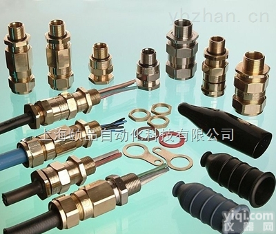
 Peppers防爆格兰头(Peppers CR-1 type glands)
 山东大量批发|BTL防爆格兰头|BTL-防爆填料函的价格(EKS打造)
 BTL-II 4分 6分 1寸双密封电缆格兰头 BTL 防爆格兰密封接...
 Peppers防爆格兰头(Peppers E1WF type glands)
 Peppers防爆格兰头(Peppers CWLE type glands)
 Peppers防爆格兰头(Peppers A2LF type glands)
 Peppers防爆格兰头(Peppers A2LDSF type glands)
 英国Peppers防爆格兰Peppers Type C- cable gland
 英国Peppers防爆格兰Peppers Type E- cable gland
 英国Peppers防爆格兰Peppers Type A- cable gland
 英国Peppers防爆格兰Peppers Type UL-U cable gland
 英国Peppers防爆格兰Peppers Type UL-C cable gland