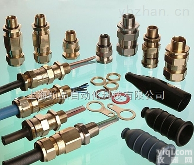
英国Peppers防爆密封接头Peppers cable Gland
上海颐品自动化,:
 |  | ||||||||||||||||||||||||
|
| “C” type single compression glands, certified Increased Safety Ex e are suitable for use in Zone 1, Zone 2, Zone 21, Zone 22 and in Gas Group II. The gland is suitable for cables that exhibit “cold flow” characteristics, whilst providing an IP66 environmental seal on the cable outer sheath and a detachable armour specific clamping system for wire (W), braid (X) or tape (Z) armoured cables. The “IE” version allows the gland to be used with HV cables where the fault load is greater than 10.4kA and options are available for use with LSOH cables and extreme temperature applications. | |||||||||||||||||||||||||
| COMPLIANCE STANDARD | EN 60079-0, EN 60079-7, EN 60079-7, EN 61241-0, EN 61241-1 IEC 60079-0, IEC 60079-7, IEC 61241-0, IEC 61241-1 & IEC 60529 |  | |||||||||||||||||||||||||||||||||||||||||||||||||||||||||||||||||||||||||||||||||||||||||||||||||||||||||||||||||||||||||||||||||||||||||||||||||||||||||||||||||||||||||||||||||||||||||||||||||||||||||||||||||||||||||||||||||||||||||||||||||||||||||||||||||||||||||||||||||||||||||||||||||||||||||||||||
| CERTIFICATION | ATEX II 2 GD Ex e II / Ex tD A21 IECEx Ex e II / Ex tD A21 GOST-R Ex e IIU CSA Ex e II Class I Zone 1 Class I Division 2, Groups A, B, C & D Class II Division 2, Groups E, F & G Class III, Enclosure Types 3, 4 & 4X NEPSI Ex e II INMETRO BR - Ex e II / Ex tD A21 ABS 1-1-4/7.7, 4.8-3/1.7, 4-8-3/13 and 4-8-4/27.5 MODU Rules 4-3-3/9 LLOYD’S Enclosure Systems (Part 1B) RMRS Part XI of Rules for sea-going ships (ed.2008) | ||||||||||||||||||||||||||||||||||||||||||||||||||||||||||||||||||||||||||||||||||||||||||||||||||||||||||||||||||||||||||||||||||||||||||||||||||||||||||||||||||||||||||||||||||||||||||||||||||||||||||||||||||||||||||||||||||||||||||||||||||||||||||||||||||||||||||||||||||||||||||||||||||||||||||||||||
| CERTIFICATE NO. | ATEX SIRA01ATEX1271X IECEx SIR 07.0097X GOST-R POCC GB.06.B00853 CSA CSA 1356011 NEPSI GYJ06187X INMETRO NCC 5878/09 X ABS 09-LD463991-PDA LLOYD’S 10/00056 RMRS 09.00784.011 | ||||||||||||||||||||||||||||||||||||||||||||||||||||||||||||||||||||||||||||||||||||||||||||||||||||||||||||||||||||||||||||||||||||||||||||||||||||||||||||||||||||||||||||||||||||||||||||||||||||||||||||||||||||||||||||||||||||||||||||||||||||||||||||||||||||||||||||||||||||||||||||||||||||||||||||||||
| APPLICATION |
| ||||||||||||||||||||||||||||||||||||||||||||||||||||||||||||||||||||||||||||||||||||||||||||||||||||||||||||||||||||||||||||||||||||||||||||||||||||||||||||||||||||||||||||||||||||||||||||||||||||||||||||||||||||||||||||||||||||||||||||||||||||||||||||||||||||||||||||||||||||||||||||||||||||||||||||||||
| IP RATING | IP66 & NEMA 4X | ||||||||||||||||||||||||||||||||||||||||||||||||||||||||||||||||||||||||||||||||||||||||||||||||||||||||||||||||||||||||||||||||||||||||||||||||||||||||||||||||||||||||||||||||||||||||||||||||||||||||||||||||||||||||||||||||||||||||||||||||||||||||||||||||||||||||||||||||||||||||||||||||||||||||||||||||
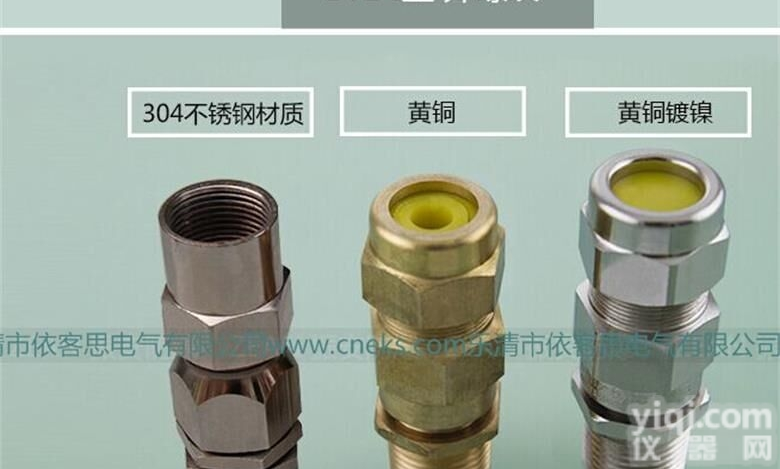
| MATERIALS | Brass or Stainless Steel | ||||||||||||||||||||||||||||||||||||||||||||||||||||||||||||||||||||||||||||||||||||||||||||||||||||||||||||||||||||||||||||||||||||||||||||||||||||||||||||||||||||||||||||||||||||||||||||||||||||||||||||||||||||||||||||||||||||||||||||||||||||||||||||||||||||||||||||||||||||||||||||||||||||||||||||||||
| VARIATIONS | Integral Earth version for HV applications: Brass (CWLIEE); 316 Stainless Steel (CWLSIEE) | ||||||||||||||||||||||||||||||||||||||||||||||||||||||||||||||||||||||||||||||||||||||||||||||||||||||||||||||||||||||||||||||||||||||||||||||||||||||||||||||||||||||||||||||||||||||||||||||||||||||||||||||||||||||||||||||||||||||||||||||||||||||||||||||||||||||||||||||||||||||||||||||||||||||||||||||||
| OPTIONS | R | Reduced Bore Seal | |||||||||||||||||||||||||||||||||||||||||||||||||||||||||||||||||||||||||||||||||||||||||||||||||||||||||||||||||||||||||||||||||||||||||||||||||||||||||||||||||||||||||||||||||||||||||||||||||||||||||||||||||||||||||||||||||||||||||||||||||||||||||||||||||||||||||||||||||||||||||||||||||||||||||||||||
| C | PVC Shroud (C) - PCP Shroud (P) - LSOH Shroud (3) | ||||||||||||||||||||||||||||||||||||||||||||||||||||||||||||||||||||||||||||||||||||||||||||||||||||||||||||||||||||||||||||||||||||||||||||||||||||||||||||||||||||||||||||||||||||||||||||||||||||||||||||||||||||||||||||||||||||||||||||||||||||||||||||||||||||||||||||||||||||||||||||||||||||||||||||||||
| K or V | Locknut, Earth Tag & Nylon (K) or Fibre (V) IP Washer | ||||||||||||||||||||||||||||||||||||||||||||||||||||||||||||||||||||||||||||||||||||||||||||||||||||||||||||||||||||||||||||||||||||||||||||||||||||||||||||||||||||||||||||||||||||||||||||||||||||||||||||||||||||||||||||||||||||||||||||||||||||||||||||||||||||||||||||||||||||||||||||||||||||||||||||||||
| S | Including Serrated Washer | ||||||||||||||||||||||||||||||||||||||||||||||||||||||||||||||||||||||||||||||||||||||||||||||||||||||||||||||||||||||||||||||||||||||||||||||||||||||||||||||||||||||||||||||||||||||||||||||||||||||||||||||||||||||||||||||||||||||||||||||||||||||||||||||||||||||||||||||||||||||||||||||||||||||||||||||||
| 1 | Quantity per kit | ||||||||||||||||||||||||||||||||||||||||||||||||||||||||||||||||||||||||||||||||||||||||||||||||||||||||||||||||||||||||||||||||||||||||||||||||||||||||||||||||||||||||||||||||||||||||||||||||||||||||||||||||||||||||||||||||||||||||||||||||||||||||||||||||||||||||||||||||||||||||||||||||||||||||||||||||
| NP | Nickel Plated (NP) - Zinc Plated (ZP) | ||||||||||||||||||||||||||||||||||||||||||||||||||||||||||||||||||||||||||||||||||||||||||||||||||||||||||||||||||||||||||||||||||||||||||||||||||||||||||||||||||||||||||||||||||||||||||||||||||||||||||||||||||||||||||||||||||||||||||||||||||||||||||||||||||||||||||||||||||||||||||||||||||||||||||||||||
| OPERATING TEMPERATURES | Standard Seals -20ºC to +85ºC Silicone Seals -60ºC to +180ºC | ||||||||||||||||||||||||||||||||||||||||||||||||||||||||||||||||||||||||||||||||||||||||||||||||||||||||||||||||||||||||||||||||||||||||||||||||||||||||||||||||||||||||||||||||||||||||||||||||||||||||||||||||||||||||||||||||||||||||||||||||||||||||||||||||||||||||||||||||||||||||||||||||||||||||||||||||
| OPTIONAL ACCESSORIES | Locknut: Brass (ACBLN) / Stainless Steel (ACSLN) Earth tag: Brass (ACBET) / Stainless Steel (ACSET) IP Washers: Nylon (ACNSW) / Fibre (ACFSW) Serrated Washer: Stainless Steel (ACSSW) Shrouds: PVC (ACSPVC) / PCP (ACSPCP) / LSOH (ACSSIO) | ||||||||||||||||||||||||||||||||||||||||||||||||||||||||||||||||||||||||||||||||||||||||||||||||||||||||||||||||||||||||||||||||||||||||||||||||||||||||||||||||||||||||||||||||||||||||||||||||||||||||||||||||||||||||||||||||||||||||||||||||||||||||||||||||||||||||||||||||||||||||||||||||||||||||||||||||
| EXAMPLE PART NUMBERING | Sample: C1WBECK1/NP/20/050NPT C Type of gland featuring armour specific clamping 1 Neoprene Seals (1) - Silicone (3) W SWA (W) / SWB (X) or STA (Z) B Brass (B) / Stainless Steel (S) IE Integral Earth E Ex e Certification R Reduced Bore Seal C PVC Shroud (C) K Nylon NP Nickel Plated 20 Gland shell size 050NPT 1/2”NPT Entry Thread | ||||||||||||||||||||||||||||||||||||||||||||||||||||||||||||||||||||||||||||||||||||||||||||||||||||||||||||||||||||||||||||||||||||||||||||||||||||||||||||||||||||||||||||||||||||||||||||||||||||||||||||||||||||||||||||||||||||||||||||||||||||||||||||||||||||||||||||||||||||||||||||||||||||||||||||||||
| |||||||||||||||||||||||||||||||||||||||||||||||||||||||||||||||||||||||||||||||||||||||||||||||||||||||||||||||||||||||||||||||||||||||||||||||||||||||||||||||||||||||||||||||||||||||||||||||||||||||||||||||||||||||||||||||||||||||||||||||||||||||||||||||||||||||||||||||||||||||||||||||||||||||||||||||||
| |||||||||||||||||||||||||||||||||||||||||||||||||||||||||||||||||||||||||||||||||||||||||||||||||||||||||||||||||||||||||||||||||||||||||||||||||||||||||||||||||||||||||||||||||||||||||||||||||||||||||||||||||||||||||||||||||||||||||||||||||||||||||||||||||||||||||||||||||||||||||||||||||||||||||||||||||
ZG区分销商:
上海颐品自动化科技有限公司
Shanghai Epin Automation Co.,Ltd.
Website:www.epinautomation。。com
:sales@epinautomation.com
全国免费:
因为专业,所以放心!
 Peppers防爆格兰头(Peppers CWLE type glands)
 山东大量批发|BTL防爆格兰头|BTL-防爆填料函的价格(EKS打造)
 BTL-II 4分 6分 1寸双密封电缆格兰头 BTL 防爆格兰密封接...
 Peppers防爆格兰头(Peppers CR-1 type glands)
 Peppers防爆格兰头(Peppers E1WF type glands)
 Peppers防爆格兰头(Peppers A2LF type glands)
 Peppers防爆格兰头(Peppers A2LDSF type glands)
 英国Peppers防爆格兰Peppers Type C- cable gland
英国Peppers防爆格兰Peppers Type E- cable gland
英国Peppers防爆格兰Peppers Type A- cable gland
英国Peppers防爆格兰Peppers Type UL-U cable gland
英国Peppers防爆格兰Peppers Type UL-C cable gland
英国Peppers防爆格兰Peppers Type C- cable gland
英国Peppers防爆格兰Peppers Type E- cable gland
英国Peppers防爆格兰Peppers Type A- cable gland
英国Peppers防爆格兰Peppers Type UL-U cable gland
英国Peppers防爆格兰Peppers Type UL-C cable gland
本产品信息由(上海颐品自动化科技有限公司)为您提供,内容包括(Peppers防爆格兰头(Peppers CWLE type glands))的品牌、型号、技术参数、详细介绍等;如果您想了解更多关于(Peppers防爆格兰头(Peppers CWLE type glands))的信息,请直接联系供应商,给供应商留言。若当前页面内容侵犯到您的权益,请及时告知我们,我们将马上修改或删除。